JOHNSON CONTROLS
38
FORM 102.20-N1
ISSUE DATE: 7/06/2016
SECTION 3 - HANDLING, STORAGE, AND INSTALLATION
c. Guide the bottom raceway/base rails togeth-
er, using rods or drift pins through the holes
in the lifting lugs on opposite sections simul-
taneously.
d. If there is any difficulty aligning the sections,
due to racking of one section or the other, use
a come-a-long diagonally on the inside of
that section at the shipping split or across the
tops of the opposite sections.
e. If there is any difficulty aligning the sections
due to the top and bottom not pulling to-
gether simultaneously, apply shims under the
sections as needed to compensate for uneven
placement area.
3. Complete pulling the sections together, using the
come-a-longs. The bolts hold the sections tight af-
ter they are pulled together.
4. Fasten the bottom lifting lugs together with the
1/2 in. x 4 in. bolts in fastener packet (P/N 386-
03418-000).
5. Fasten the top raceway bracket with the 1/2 in. x
5-1/2 in. bolts provided in fastener packet (P/N
386-03418-000).
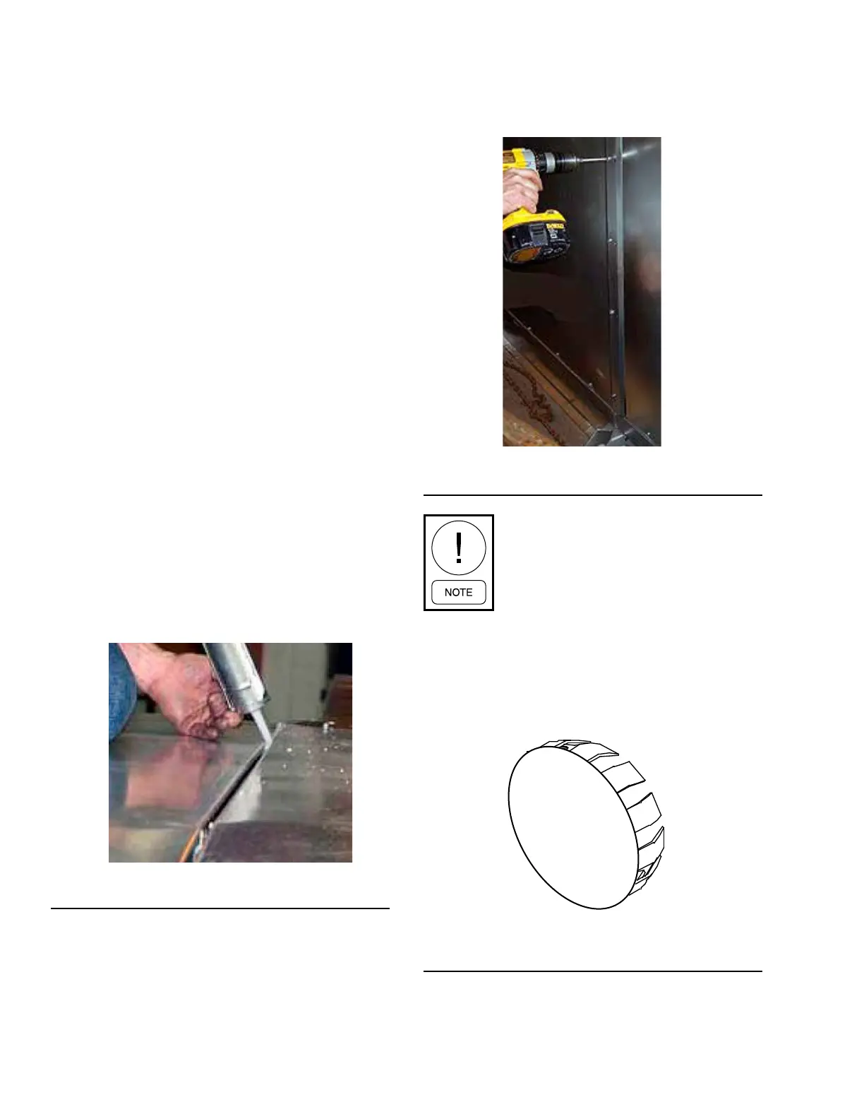
6. Apply a 1/4 in. bead of caulking to exterior of the
seam on the roof and both sides as shown in Fig-
ure 50 on page 38. Repeat the process for the
seamontheoorinsidetheAHU.
FIGURE 50 - APPLYING CAULK TO SEAMS
LD13776
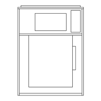
7. Apply neoprene gasket (P/N 028-15954-010) to
the underside of the seam caps, and install them
over the joints with hex head screws (P/N 386-
04747-000) as shown in Figure 51 on page 38.
Painted seam caps are applied over the joints on
the sides and roof of the exterior, and galvanized
seamcapsareappliedontheinteriorooronly.
FIGURE 51 - INSTALLING GASKETS
LD13778
If a roof seam cap has a tab only on one
end, the end without the tab goes above
the pipe chase location.
8. Repeat this procedure for each additional section.
9. For AHUs or sections without base rails, install
the corner connector hole plugs (P/N 021-19568-
000) as shown in Figure 52 on page 38 on the
bottom raceway corners.
FIGURE 52 - SOLUTION XT CORNER CONNECTOR
HOLE PLUG (P/N 021-19568-000)
LD116514

 Loading...