JOHNSON CONTROLS
98
FORM 102.20-N1
ISSUE DATE: 7/06/2016
SECTION 3 - HANDLING, STORAGE, AND INSTALLATION
Filter Installation
Installing a 2 in. Pleated Filter
Use the following instructions to install a 2 in. Multi-
Pleat Elite filter into a 16 g galvanized holding frame
with four latches (P/N 026-35788-702), as shown in
Figure 147 on page 95.
1. Install one latch at each corner (4 corners) of the
frame.Thelatchtsintotworowsofthreeknock-
outs. Use the row of knockouts closest to the gas-
ketfornominal1in.ltersorlterswitha13/16
in. single header. Use the second set of knockouts
fornominal2in.lters.
2. Insert the straight end of the latch between the two
knockouts furthest from the corner.
3. Using a moderate amount of pressure, force the
latch over the third knockout. The latch should
now be trapped within the three knockouts, but
should be able to freely rotate as shown in Figure
148 on page 98.
4. The latch installation should be complete.
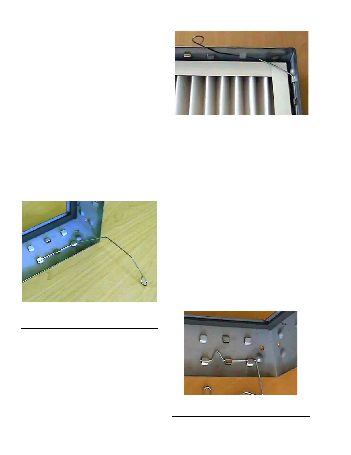
FIGURE 148 - CORRECTLY INSTALLED LATCH PIN
(P/N 026-35788-702)
LD10171
5. Install the other three latches into the corners.
6. Rotate all of the latches outward, and insert the
lterintotheframe.
7. Grasp the circular end of the latch, and rotate it
acrossthecornerofthelter.
8. Pushtheendofthelatchtowardsthelteruntilthe
latch catches beneath the knockout on the frame.
9. Repeat the process with the remaining latches.
10. The lter should now be securely installed into
the frame as shown in Figure 149 on page 98.
FIGURE 149 - FULLY INSTALLED FILTER
LD10174
Installing a 4 in. Pleated Filter
Use the following instructions to install a 4 in Micro-
MAX filter into a 16 g galvanized holding frame with
four latches (P/N 026-35778-604), as shown in Figure
147 on page 95.
1. Install one latch at each corner (4 corners) of the
frame.Thelatchtsintotworowsofthreeknock-
outs. Use the row of knockouts closest to the gas-
ketfornominal1in.ltersorlterswitha13/16
in. single header. Use the second set of knockouts
fornominal2in.lters.
1. Insert the straight end of the latch between the two
knockouts furthest from the corner.
2. Using a moderate amount of pressure, force the
latch over the third knockout. The latch should
now be trapped within the three knockouts, but
should be able to freely rotate as shown in Figure
150 on page 98.
3. The latch installation should now be complete.
FIGURE 150 - CORRECTLY INSTALLED LATCH PIN
(P/N 026-35788-604)
LD10177

 Loading...