JOHNSON CONTROLS
67
SECTION 3 - HANDLING, STORAGE, AND INSTALLATION
FORM 102.20-N1
ISSUE DATE: 7/06/2016
3
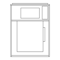
FIGURE 103 - TYPICAL POWER WIRING OF
ENERGY RECOVERY WHEEL
LD12591
WIRING THE GAS HEAT DEVICE
It is the installer's responsibility to wire this device, if
the single point power connection was not purchased.
Panel locations and sizes vary based upon the AHU's
size and burner configurations. Burner voltage is se-
lected to match the primary AHU voltage. Modulation
control voltage 2-10 VDC is standard.
Electrical penetrations can come through the floor or
side wall panels. Drill and properly seal any penetra-
tions to keep out moisture. Refer to the service manual
for more information.
Make power connections per the wiring diagrams pro-
vided on the inside of the burner control panel. Refer to
the Air Handling Units - Operation and Maintenance
Manual (Form 102.20-OM2) for more information.
FIGURE 105 - MAIN POWER AND CONTROL
PANEL WITH COVER OPEN
LD11597
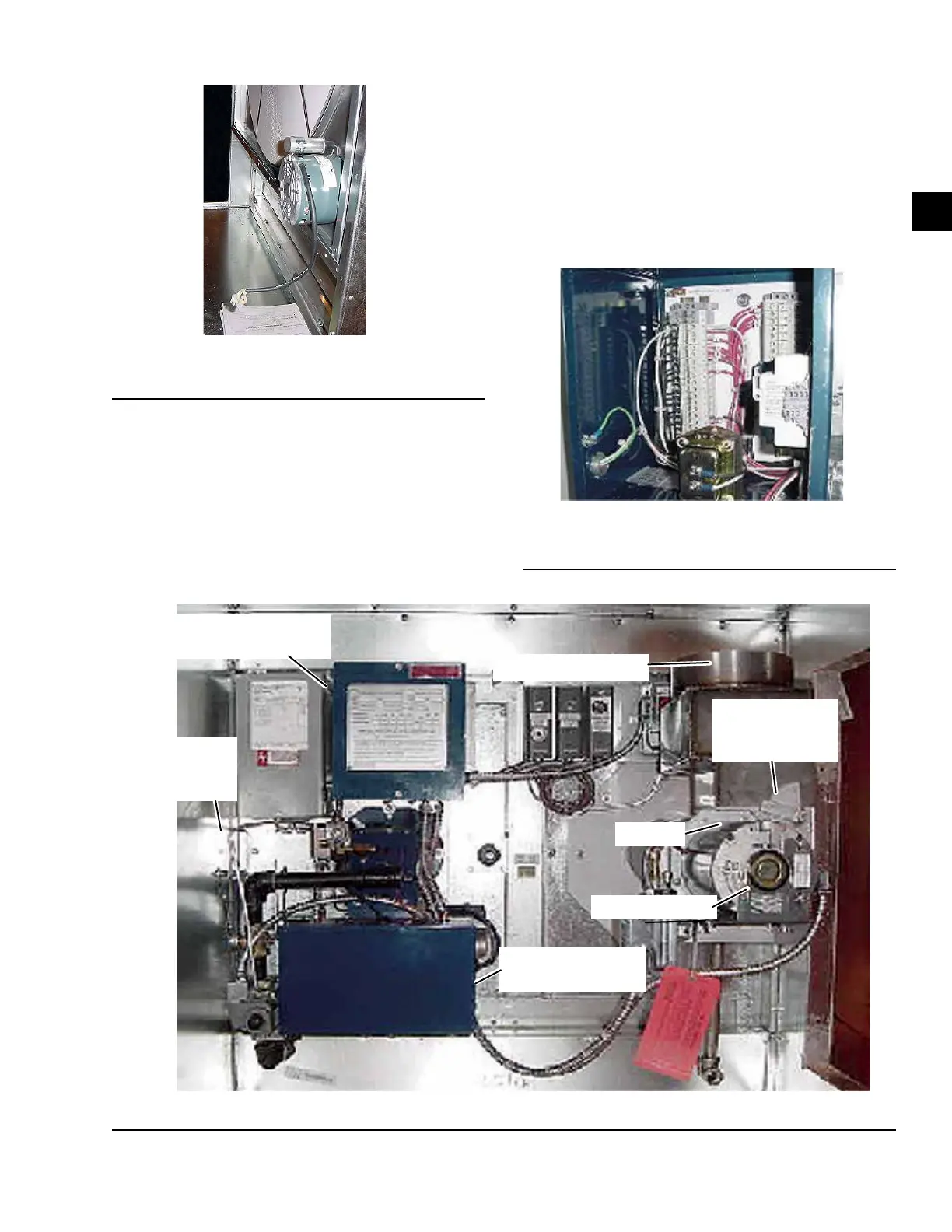
FIGURE 104 - GAS BURNER COMPONENT LOCATIONS
LD11596b
MAIN POWER AND CONTROL
TERMINATION PANEL
INSIDE GAS
BURNER PIPE
CHASE
BURNER CONTROL
PANEL
FLUE CONNECTOR
ID FAN
ID FAN MOTOR
DRAFT DAMPER
ADJUSTABLE
QUADRANT

 Loading...