JOHNSON CONTROLS
36
FORM 102.20-N1
ISSUE DATE: 7/06/2016
SECTION 3 - HANDLING, STORAGE, AND INSTALLATION
9. Make sure all wiring and/or control tubing con-
nection pigtails are secured out of the path of the
shipping split mating surfaces to prevent damage.
10. Apply separate gasket squares (P/N 028-11883-
010) as shown in Figure 43 on page 36. Place
one square at each corner of the face of each sec-
tion.
11. Apply neoprene gasket (P/N 028-11883-010 or
P/N 028-11873-010) to face the perimeter from
square to square, and 1/4 in. from the outside edge
of the mating surface (nearest to AHU exterior)
to allow for a 1/4 in. bead of caulk. The gasket
application should provide a continuos seal from
side-to-side, and to the top of the AHU roof to the
bottom of the AHU base where it meets the curb.
12. Apply a 1/2 in. thick bead of caulk (not provided),
tothecurbtopsurfaceonly,wheretherstsection
will be placed.
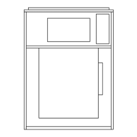
FIGURE 43 - APPLYING GASKET SQUARE,
NEOPRENE GASKET AND CAULK TO RACEWAY
SPLIT
LD13372
NEOPRENE
GASKET
GASKET
SQUARE
RACEWAY
SPLIT
CAULK
Setting Up the Sections
Use the following instructions to set up the sections.
1. Placethe rstsectionon thecurb.Positionitso
that the overhanging curb rest is spaced evenly
from the curb on each side and end.
2. Aftertherstsectionisplaced,anchor,orblockit
before setting the next section.
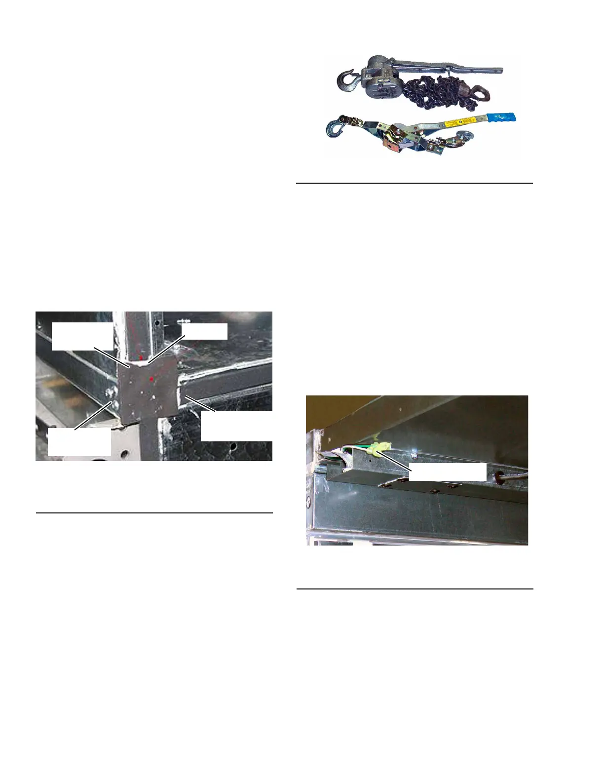
3. Attach the come-a-longs (power pulls) as shown
in Figure 44 on page 36 totherstsection.Use
lifting lugs on the base rail (not at the shipping
split) or holes in the two outside corners.
FIGURE 44 - TYPICAL COME-A-LONGS
LD09613a
4. Apply a 1/2 in. thick bead of caulk to the curb top
surface in the area where the next section will be
placed.
5. Place the next section on the curb about 4 in. from
therstsection.
6. Feed the electrical and control connections from
section to section and make sure that they will be
accessible after the sections are joined as shown
in Figure 45 on page 36.
7. Assemble the electrical connectors and/or pneu-
matic tubes as shown in Figure 46 on page 37
according to their labels before joining sections, if
access will be a problem later.
FIGURE 45 - ELECTRICAL CONNECTOR (NOT
CONNECTED)
LD13373a
CONNECTOR

 Loading...