JOHNSON CONTROLS
90
FORM 102.20-N1
ISSUE DATE: 7/06/2016
SECTION 3 - HANDLING, STORAGE, AND INSTALLATION
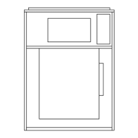
FIGURE 138 - DRAIN TRAP SHOWING WATER
LOCATION FOR DRAW THROUGH OPERATION
LD06342
Drain
Pan
Drain
Nipple
Drain
Pan
Drain
Pan
NO.1 - Fan Off
NO. 2 - Trap Condition When Fan Starts
NO. 3 - Fan Running And Condensate
Cooling Coil
Drain Pan
Trap
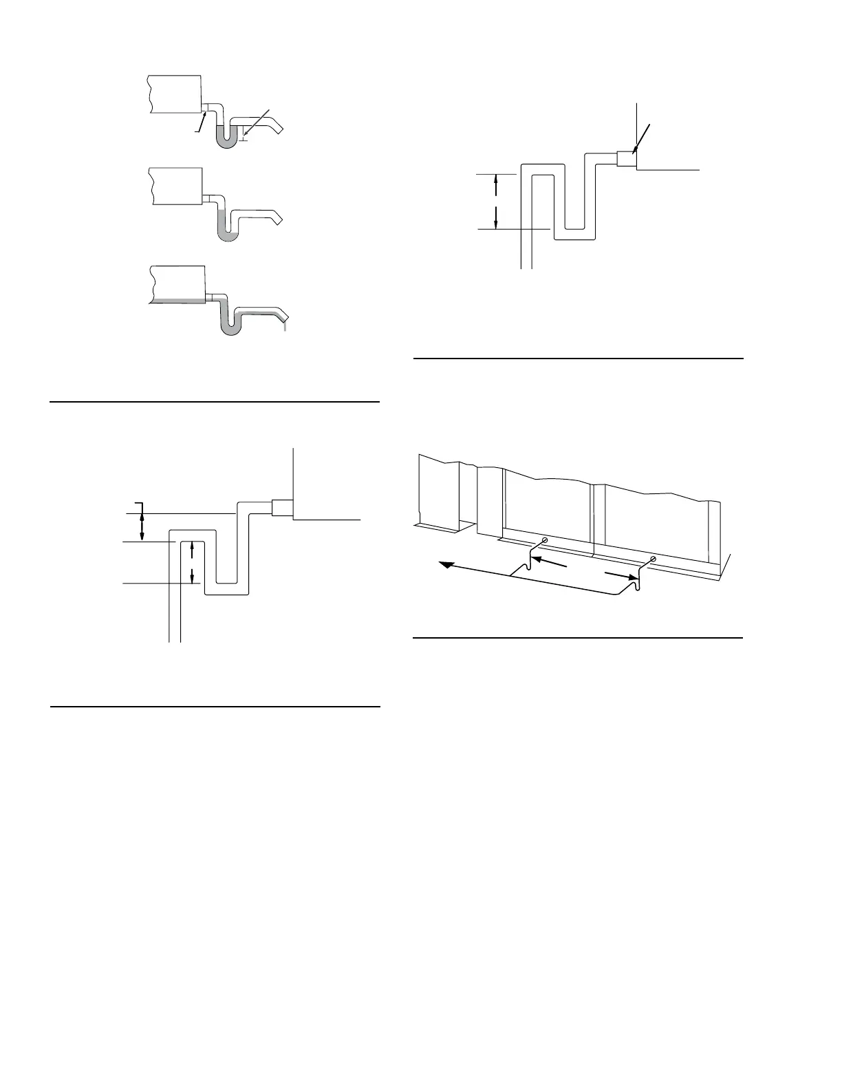
FIGURE 139 - TRAP DETAIL FOR DRAIN PAN IN
NEGATIVE ENVIRONMENT (DRAW THROUGH)
LD05370
H Must Be At Least
1 Plus Fan Total
Static Pressure
H
X= 1/2 H
X
Condensate Drain Trap
For Draw Through applications, install a trapped con-
densate drain line at the AHU drain connection as
shown in Figure 139 on page 90, according to all
codes. The H dimension must be at least 1 in. greater
than the design TSP of the fan, which ensures proper
drainage even if filters clog or dampers malfunction.
For Blow Through applications, the same principles
apply, but the leaving pipe should be as shown in Fig-
ure 140 on page 90 for proper trap design.
FIGURE 140 - TRAP DETAIL FOR DRAIN PAN IN
POSITIVE ENVIRONMENT (BLOW THROUGH)
LD05371
H Must Be A Least 1 Inch Plus
Fan Total Static Pressure
H
Top Of Trap Must Be Equal To Or Lower
Than Bottom Of Unit Drain Connection
Drain
Connection
Two or more drains on the same side of AHU must be
trapped individually before the drain lines can be com-
bined and routed to a suitable drain as shown in Figure
141 on page 90.
FIGURE 141 - COMBINING DRAIN LINES
LD06345
Traps
If the distance from the drain pan outlet to the trap
exceeds 10 ft, install additional clean outs for each 10
ft segment of horizontal drain line (min. 1/4 in per foot
fall required). On initial start-up, it may be necessary to
fill the trap manually.
Elevating AHU for Gravity Floor Drain
Connections
On indoor AHUs, the installer must provide a method
to pump or drain the coil condensate water away from
the AHU. The installer may have to elevate the AHU to
provide space below the condensate drain of the AHU
to properly install the designed drain trap(s) to permit
gravity flow of condensate water from the drain pan as
shown in Figure 17 on page 28.

 Loading...