JOHNSON CONTROLS
18
FORM 160.84-N1
ISSUE DATE: 11/22/2016
SECTION 2 - RIGGING AND LIFTING
FORM 3 SHIPMENT
The chiller is shipped in five major assemblies:
• The evaporator/condenser shell assembly.
• The driveline (compressor/motor assembly).
• The Variable Speed Drive (VSD).
• The OptiView™ Control Center assembly.
• The Power Panel assembly.
• Miscellaneous shipped loose items.
One lifting chain is required for each
lifting point and each chain having a
working load limit 40% of condenser and
evaporator weight or heat exchanger be-
ing lifted.
The lifting chains traversing the evapora-
tor/condenser shells should remain 90°
+/- 10° from horizontal. A spreader bar
may be required to achieve the +/- 10°.
Refrigerant charges are shipped separately.
Arrangements with the local service ofce
must be made to ensure refrigerant is on-
site when the unit is ready to be charged.
When optional skids are used it may be
necessary to remove the skids so riggers
skates can be used under the unit end
sheets to reduce overall height.
Shells
1. Attach rigging chains to an adequate lifting device.
2. Attach chains to the lifting holes at the corner of
each end sheet as shown on Figure 5 on page 19.
3. If necessary to avoid contact with chiller compo-
nents install side spreader bars between the Evap-
orator and Condenser end sheet lifting chains.
4. The angle of the lifting chains traversing the en
sheet should not be less than 65° as shown on Fig-
ure 5 on page 19.
5. With an adequate lifting device lift the unit slight-
ly off the ground to determine adjustments neces-
sary to keep the unit level. Make adjustments as
necessary to level the unit.
Compressor Motor Assembly
TABLE 1 - COMPRESSOR MOTOR WEIGHTS
Compr Code Pounds Kilograms
M2C-197FAC 2,861 1298
M2C-197FACD 2,861 1292
M2C-205FAC 2,867 1300
M2C-205FACD 2,867 1295
M2C-218FAC 2,987 1355
M2C-233FAC 2,999 1,360
M2C-246FAC 2,989 1,356
M6C-295FAC 4,298 1,950
M6C-331FAC 4,500 2,041
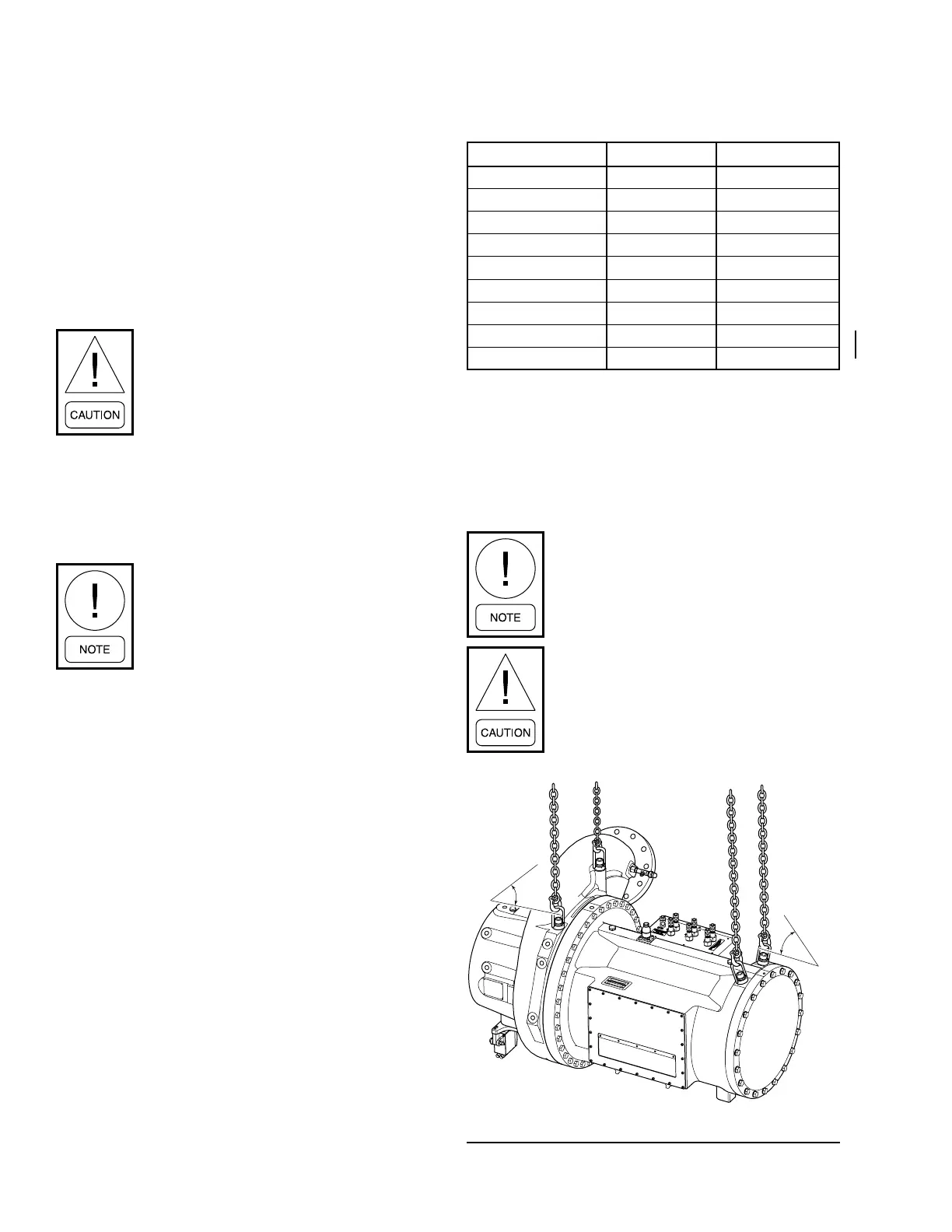
1. Attach rigging chains to each end of the com-
pressor/motor assembly as shown in Figure 4 on
page 18.
2. Lift the compressor/motor assembly off the
ground to check for center of gravity. Make ad-
justments as necessary.
The M2C and M6C Compressor/Motor
has metric lifting lugs
Use lifting chains with working load limit
each 70% of total driveline weight.
FIGURE 4 - DRIVELINE RIGGING
LD17276b
45°
Min.
45°
Min.

 Loading...


