JOHNSON CONTROLS
21
SECTION 2 - RIGGING AND LIFTING
FORM 160.84-N1
ISSUE DATE: 11/22/2016
2
FORM 7 SHIPMENT
The chiller is shipped in six assemblies:
• The driveline (compressor/motor assembly).
• The evaporator.
• The condenser.
• The Variable Speed Drive (VSD).
• The OptiView™ Control Center assembly.
• The Power Panel assembly.
• Miscellaneous shipped loose items.
Refrigerant charges are shipped separately.
Arrangements with the local service ofce
must be made to ensure refrigerant is on-
site when the unit is ready to be charged.
When optional skids are used it may be
necessary to remove the skids so riggers
skates can be used under the unit end
sheets to reduce overall height.
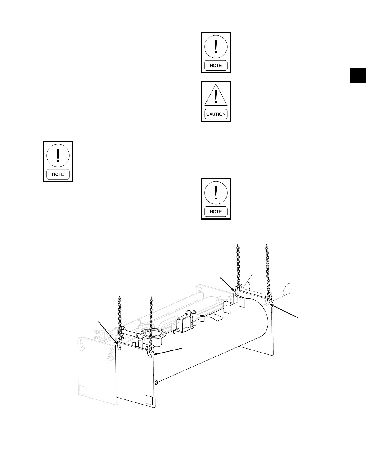
FIGURE 9 - FORM 7 RIGGING WITH SIDE SPREADER BARS
LD17059b
45°
Min.
EVAPORATOR
CONDENSER
Lifting
Holes
Lifting
Holes
Lifting
Holes
Lifting
Holes
90°+/-10°
The lifting chains along the axis of the
evaporator/condenser shells should not
exceed 90° +/- 10°. A spreader bar may
be required to achieve the +/- 10°.
One chain is required per each lifting
point.
Use lifting chains with working load limit
each at least 40% of the total shell weight.
Condenser
1. Attach rigging chains to an adequate lifting device.
2. Attach chains to the two lifting holes at the corner of
each end sheet as shown in Figure 9 on page 21.
Angles apply to condenser or evaporator.

 Loading...


