JOHNSON CONTROLS
41
FORM 160.84-N1
ISSUE DATE: 11/22/2016
4
SECTION 4 - REASSEMBLY
Form 3 and Form 7 Reassembly
Refer to Figure 29 on page 43, Figure
30 on page 44, Figure 31 on page 45,
Figure 32 on page 46 and Figure 33
on page 47 for reassembly hardware
identication.
1. Rig shells according to the rigging section to nal
location. See Section 2 - Rigging and Lifting.
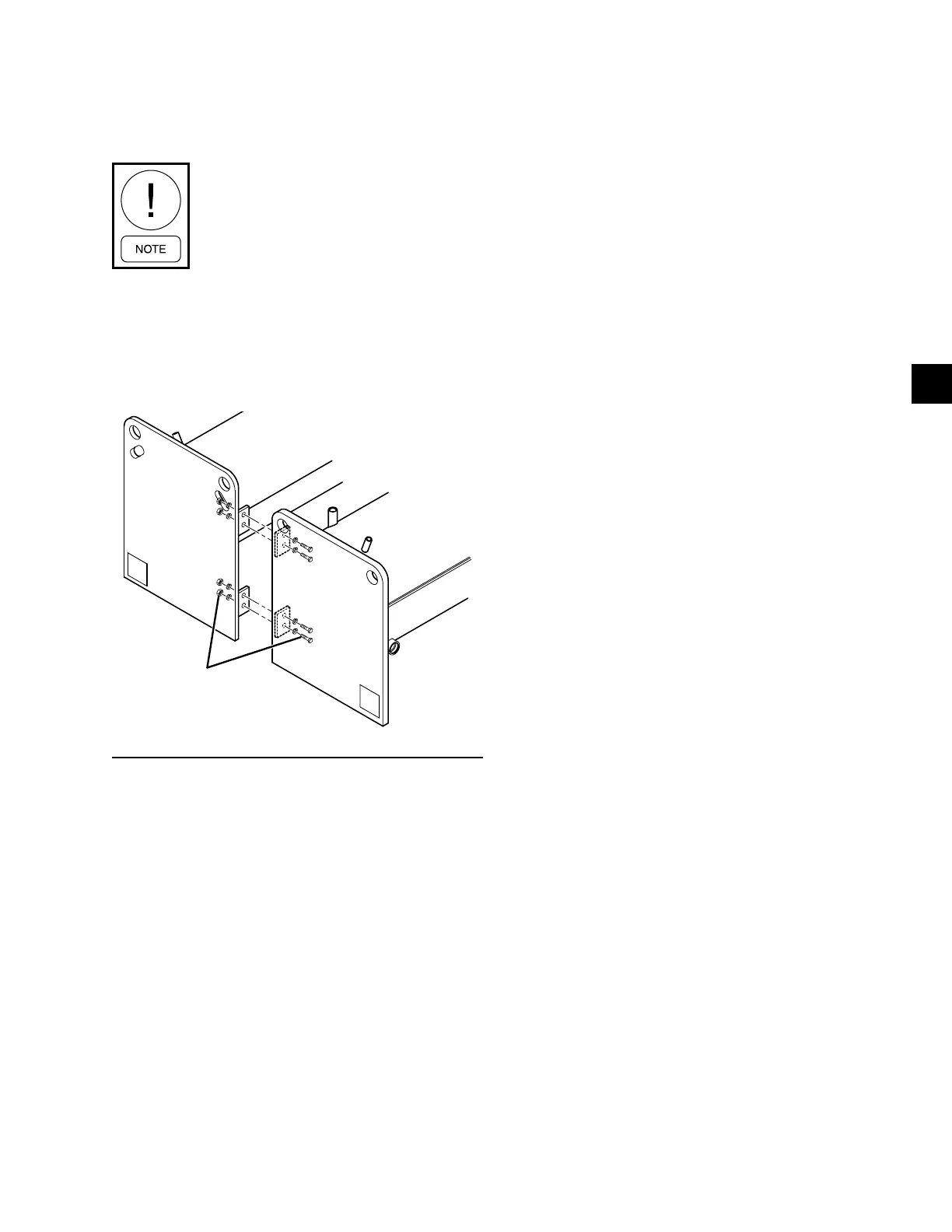
2. Bolt the tube sheets together as shown in Figure
28 on page 41. Note that the outside surfaces of
the tube sheets must be ush.
FIGURE 28 - SHELL REASSEMBLY
CONDENSER
5/8” x 2-1/2”
Bolts, Lockwashers,
and Hex Nuts
EVAPORATOR
LD14812
3. Assemble vibration isolators to unit. Refer to In-
stall Isolators on page 31.
4. Level shells in both directions. The longitudi-
nal alignment of the shell should be checked by
placing a level on the top of the shell, next to the
discharge connection. The transverse alignment
should be checked by placing a level on the tops
of both end sheets. Refer to Section 3 - Installa-
tion on page 31 for additional instructions to
level the unit. After shell is leveled, wedge and
shim each corner of the shell to solidly support it
while assembling the other parts.
5. Install the discharge piece and optional isolation
valve between the compressor and the condenser
using proper gaskets and hardware.
6. Lift compressor/motor assembly according to rig-
ging section and remove packing materials. Care-
fully lower the compressor/motor assembly on to
the discharge line and motor support on the evap-
orator. Fasten compressor/motor assembly with
the proper hardware. Do not tighten the bolts until
all connections are made to the compressor.
7. Bolt the suction line between the compressor and
the evaporator using proper gaskets and hardware.
8. Complete the refrigerant liquid line piping be-
tween the evaporator and condenser. Be sure
hardware are all properly installed.
9. Tighten all hardware installed in steps 3 through
6 above to the specied torque values provided in
the reassembly gure.
10. Install refrigerant piping (Refer to Refrigerant
Tubing Reassembly on page 52).
11. Pressure test the unit with nitrogen per Form
160.84-O1.
12. Lift the Variable Speed Drive in accordance with
rigging instructions and remove all packing ma-
terial. Carefully lower the Variable Speed Drive
on to the supports on the condenser. Fasten the
Variable Speed Drive to the condenser. Make all
necessary connections for the VSD cooling loop
to be complete.
The Variable Speed Drive will be shipped with
glycol in the cooling system. The Variable Speed
Drive coolant must be changed to the inhibitor
provided with the shipped loose items prior to
starting the unit or a VSD over temperature fault
may occur.
13. Lift the OptiView Control Center in accordance
with rigging instructions and remove all pack-
ing material. Carefully lower the control panel on
to the supports provided on the condenser. Fas-
ten the Control Center to the condenser with the
proper hardware.
14. Re-connect motor power leads in the Variable
Speed Drive to T1, T2, and T3 terminals and
torque to 18-20 Ft-lbs. per the labels in the VSD.
15. Connect the motor terminal box ex duct to the
drive.

 Loading...


