JOHNSON CONTROLS
55
FORM 160.84-N1
ISSUE DATE: 11/22/2016
5
SECTION 5 - DIMENSIONS, NOZZLE ARRANGEMENTS AND WEIGHTS
COMPRESSOR UNIT DIMENSIONS
ADDITIONAL OPERATING HEIGHT CLEARANCE TO FLOOR FT - IN (MM)
Type Of Chiller Mounting M
Neoprene Pad Isolators 1 - 3/4" (45)
Spring Isolators 1" Deection 1" (25)
Direct Mount 3/4" (19)
EVAPORATOR
CODE
CONDENSER
CODE
DIMENSIONS - 197 - 246 COMPRESSOR UNITS FT - IN (MM)
A
B
C D E
490 VSD 774 VSD
EB2508 CC2508
5'-5"
(1651)
6'-1/2"
(1842)
—
1'-3/8"
(419)
1'-1/2"
(457)
8'
(2438)
EB2510 CB2110
5'-5-1/4"
(1657)
6'-9-9/32"
(2065)
7'-11
(2419)
1'-4-5/8"
(406)
1'-4-5/8"
(422)
10'
(3048)
EB2510 CB2510
5'-5-1/4"
(1657)
6'-7-11/16"
(2024)
7'-9-11/16"
(2380)
1'-4-5/8"
(406)
1'-4-5/8"
(422)
10'
(3048)
EB2514 CB2514
5'-5-1/4"
(1657)
6'-7-11/16"
(2024)
7'-9-11/16"
(2380)
1'-4-5/8"
(406)
1'-4-5/8"
(422)
14'
(4267)
EB2910 CB2510
5'-7"
(1702)
6'-9-15/16"
(2081)
7'-9-5/8"
(2378)
1'-4"
(406)
1'-5-1/2"
(445)
10'
(3048)
EB2910 CB2910
5'-10"
(1778)
7'-2-3/8"
(2194)
8'-1-7/8"
(2486)
1'-5-1/2"
(445)
1'-5-1/2"
(445)
10'
(3048)
EB2914 CB2514
5'-7"
(1702)
6'-9-15/16"
(2081)
7'-9-5/8"
(2378)
1'-4"
(406)
1'-5-1/2"
(445)
14'
(4267)
EB2914 CB2914
5'-10"
(1778)
7'-2-3/8"
(2194)
8'-1-7/8"
(2486)
1'-5-1/2"
(445)
1'-5-1/2"
(445)
14'
(4267)
EB3310 CB2910
6'-2"
(1880)
7'-2-3/8"
(2194)
8'-1-7/8"
(2486)
1'-5-1/2"
(445)
1'-7-1/2"
(495)
10'
(3048)
EB3310 CB3310
6'-7"
(2007)
7'-3-3/8"
(2219)
8'-5-5/16"
(2573)
1'-8" (508)
1'-7-1/2"
(495)
10'
(3048)
EB3314 CB2914
6'-2"
(1880)
7'-2-3/8"
(2194)
8'-1-7/8"
(2486)
1'-5-1/2"
(445)
1'-7-1/2"
(495)
14'
(4267)
EB3314 CB3314
6'-7"
(2007)
7'-3-3/8"
(2219)
8'-5-5/16"
(2573)
1'-8" (508)
1'-7-1/2"
(495)
14'
(4267)
NOTES:
1. See Figure 43 on page 56 for dimension location points as designated on this table.
2. All dimensions are approximate. Certied dimensions are available on request.
3. Standard water nozzles are Schedule 40 pipe size, furnished as welding stub-outs with ANSI/AWWA C-606 grooves, allowing the option
of welding, anges, or use of ANSI/AWWA C-606 couplings. Factory-installed, class 150 (ANSI B16.5, round slip-on forged carbon steel
with 1/16" raised face), water anged nozzles are optional (add 1/2" to nozzle length). Companion anges, nuts, bolts, and gaskets are not
furnished.
4. One, two, and three-pass nozzle arrangements are available only in pairs shown for all shell codes. Any pair of evaporator nozzles may
be used in combination with any pair of condenser nozzles Compact water boxes on one heat exchanger may be used with Marine Water
Boxes on the other heat exchangers.
5. Condenser water must enter the water box through the bottom connection for proper operation of the sub-cooler to achieve rated performance.
6. To determine overall height, add dimension "M" for the appropriate isolator type.

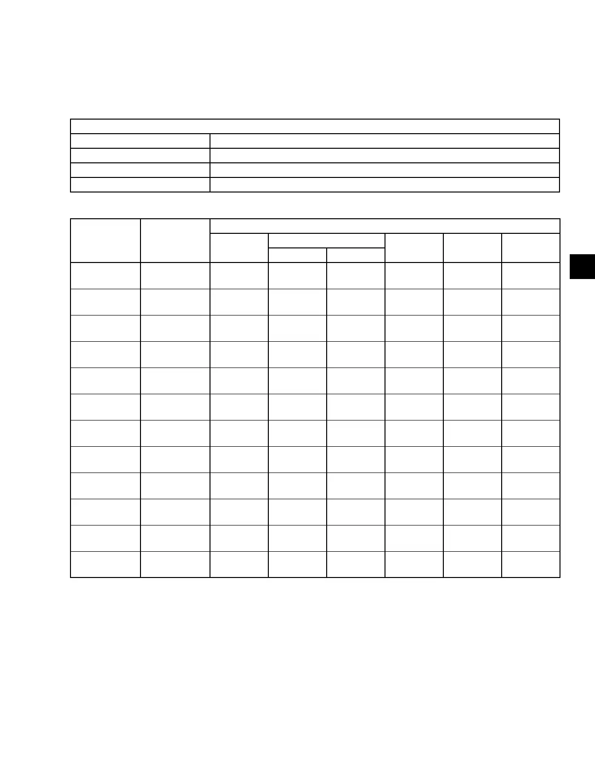 Loading...


