JOHNSON CONTROLS
23
SECTION 2 - RIGGING AND LIFTING
FORM 160.84-N1
ISSUE DATE: 11/22/2016
2
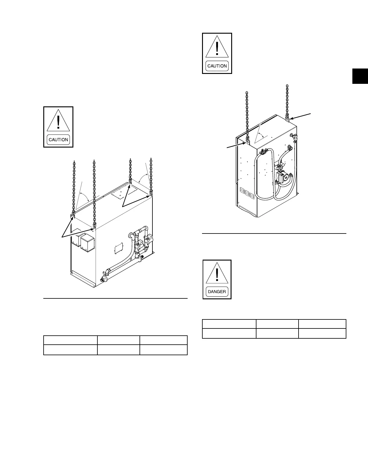
1. Attach rigging chains from an adequate lifting de-
vice to the four lifting holes at the top of the VSD
as shown in Figure 11 on page 23.
2. Lift the VSD slightly off the ground to check for
center of gravity. Make adjustments as necessary
to level the VSD.
3. Lift the VSD and remove all packing material, for
VSD weight refer to Table 6 on page 22.
Use lifting chains with working load limit
each 35% of total VSD weight.
FIGURE 11 - VARIABLE SPEED DRIVE RIGGING
Lifting
Holes
65°
Min.
65°
Min.
Power Panel
TABLE 7 - POWER PANEL
Description Pounds Kilograms
Power Panel 300 135
1. Attach rigging chains to an adequate lifting device.
2. Attach the chains to the lifting holes at the top
of the Power Panel as shown in Figure 12 on
page 23.
3. Lift the Power Panel slightly off the ground to
check for center of gravity. Make adjustments as
necessary to level the Power Panel.
4. Lift the Power Panel and remove all packing
material.
Use lifting chains with working load limit
each 70% of the Power Panel weight.
FIGURE 12 - POWER PANEL
LD17275a
Lifting
Holes
Lifting
Holes
45°
Min.
OptiView™ Control Center
The OptiView™ Control Center weighs
over 50 pounds and a technician and
helper are needed for the installation of
the panel.
TABLE 8 - CONTROL PANEL WEIGHTS
Description Pounds Kilograms
OptiView 75 34
1. Lift the OptiView™ Control Center and remove
all packing material.
2. Carefully lower the OptiView™ Control Center
on to the supports on the condenser.
3. Attach the OptiView™ Control Center to the con-
denser with the proper hardware.

 Loading...


