JOHNSON CONTROLS
50
FORM 160.84-N1
ISSUE DATE: 11/22/2016
SECTION 4 - REASSEMBLY
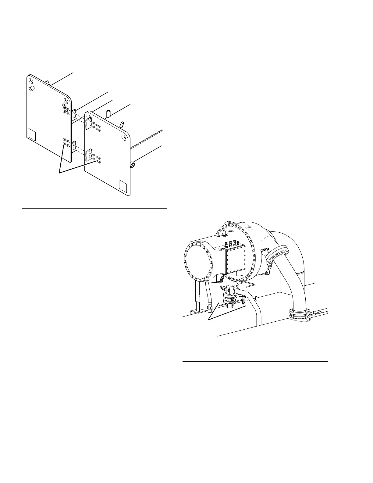
Form 11 Reassembly
1. Bolt the tube sheets together as shown in Figure
35 on page 50. Note that the outside surfaces of
the tube sheets must be ush.
FIGURE 35 - SHELL REASSEMBLY
CONDENSER
5/8” x 2-1/2”
Bolts, Lockwashers,
and Hex Nuts
EVAPORATOR
LD14812
2. Assemble vibration isolators to unit. Refer Sec-
tion 3 - Installation on page 31.
3. Level shells in both directions. The longitudi-
nal alignment of the shell should be checked by
placing a level on the top of the shell, next to the
discharge connection. The transverse alignment
should be checked by placing a level on the tops
of both end sheets. Refer Section 3 - Installation
on page 31 for additional instructions to level
the unit. After shell is leveled, wedge and shim
each corner of the shell to solidly support it while
assembling the other parts.
4. Install the discharge piece and optional isolation
valve between the compressor and the condenser
using proper gaskets and hardware.
5. Complete the refrigerant liquid piping between
the evaporator and condenser. Be sure hardware
are all properly installed.
6. Tighten all hardware installed to the specied
torque values provided on Figure 37 on page 51.
7. The Variable Speed Drive will be shipped with
glycol in the cooling system. The Variable Speed
Drive coolant must be changed to the inhibitor
provided with the shipped loose items prior to
starting the unit or a VSD over temperature fault
may occur.
8. Re-connect motor power leads in the Variable
Speed Drive to T1, T2, and T3 terminals and
torque to 18-20 Ft-lbs. per the labels in the VSD.
9. Re-connect all unit wiring and harnesses (refer to
YMC
2
Unit Wiring and Field Control Modica-
tions (Form 160.84-PW2).
10. Install refrigerant piping (refer to Refrigerant Tub-
ing Reassembly section of this manual for proper
connection of O-ring ttings).
11. Pressure test the unit with nitrogen per Form
160.84-O1.
12. Remove Nitrogen and charge unit with refrigerant
(refer Form 160.84-OM1).
LD17280
3/8”
Steel
Piping
FIGURE 36 - REFRIGERANT PIPING
13. Complete installation and nally level the unit per
Installation Instruction. Refer Section 3 - Installa-
tion on page 31.

 Loading...


