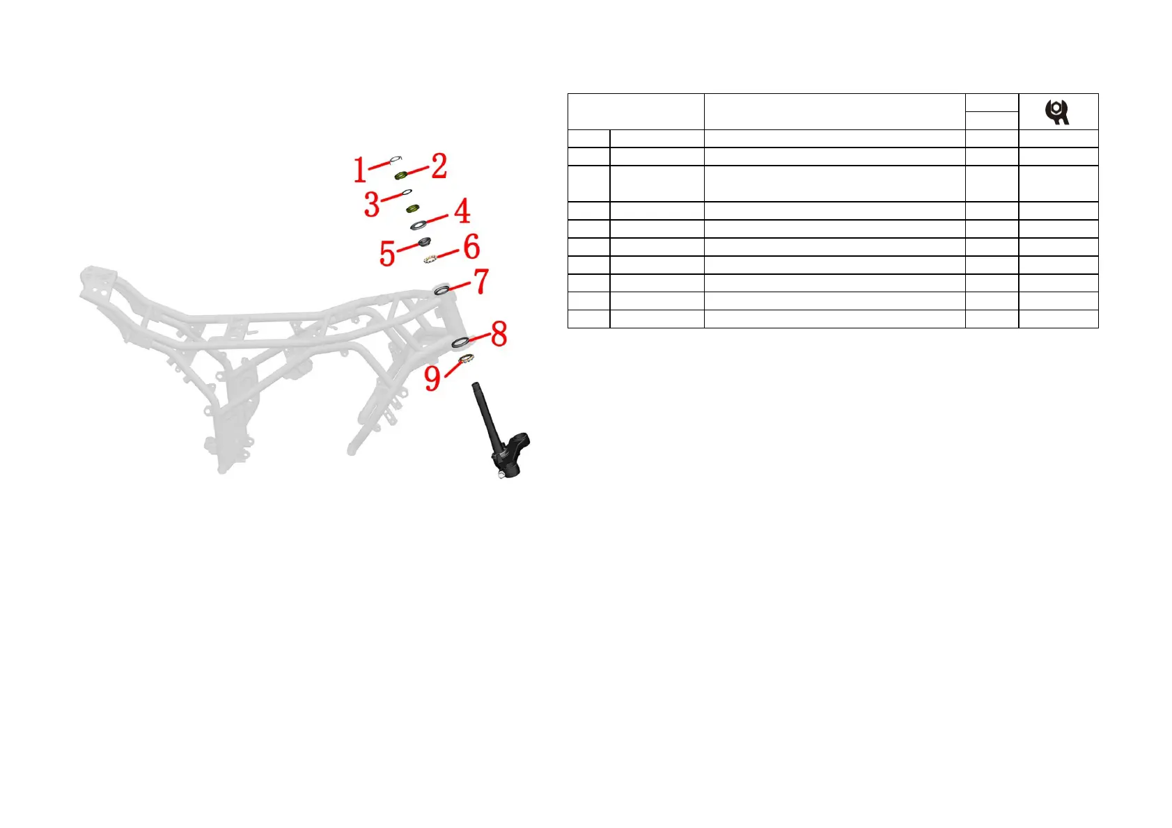
1-FRAME&ELECTRONIC COMPONENT 9
CHK
ADJ
NO. PART NO.
1 1134100-007000
ZT250-S Adjusting nut locking washer
1
3 1244100-015000
ZT250-S Adjusting nut rubber pad
1
4 1244300-014000
ZT350-R upper dust cover
1
5 1130900-024000
6 1130900-022000
ZT250-S conjoined steel ball
1
7 1130900-026000
ZT250-S upper steel bowl
1
8 1134300-001000
9 1134300-002000
ZT350-R conjoined steel ball
1
CAUTION:
●Remove the head part component, handlebarcomponent and front shock absorber component first.
●Please pay attentin to fix the awaiting repair motorcycles during disassembly,prevent dumping by
accident.
●Please check whether the steel beads of the conjoined body have abnormal phenomena such as
partial abrasion and rust.If YES, please buy the regular accessories, if not, please be sure to grease the
old grease and repaint the lubricating grease on it.
●It must be to check whether the steel ball is available during reassembly.
●It must be reasonable to adjust the steering, too loose will cause the locomotive to brake slightly,
and the locomotive will shake slightly, too tight can lead to inflexibility, resulting in safety hazards.
●If you have the ability and the right tool, you can change the shaft ring and the dustproof cover
.During the replacement process, pay attention to the protection of the lower connected plate. After
replacement, it must be to check the parallelism of the column and the damping hole, the vertical
degree of the vertical column and the lower connected plate.
PROCEDURE:
●Dissembly
Remove the lock washer⑴.
Remove the top adjusting nut ⑵ by using a special four-jaw or hook wrench tools.
Remove the rubber pad ⑶.
With one hand to hold down the down connected plate assembly, the other hand use a special four-jaw set
or hook wrench to remove the adjusting nut⑵.
Remove the down connected plate component.
Remove the upper dustproof cover⑷.
Remove the axletee ring ⑸ of the upper riser and the steel ball⑹.
Remove the steel ball of the down connected plate component⑼.
●Assemble
When reassembling, the conjoined steel beads should be painted lubricating grease,attention to the dosage.
The torque of rating nut which closes to upper dustproof cover is required to about 14N·m.so as to be able to
rotate out of nimbleness.
The top adjusting nut only needs to rotate to the bottom of the nut groove alignment, not too tight to
prevent the rubber pad ⑶ from deformation too larg.
Fig.4 FRAME&ELECTRONIC
COMPONENT
22
Directional column component
ZT250-S direction column adjusting screw nut M24×1
(environmental color Zinc)
1251300-046093

 Loading...