1-FRAME&ELECTRONIC COMPONENT 7
CHK
ADJ
NO. PART NO.
1
1251300-063093
Plywood M6×11×15(color Zinc) 4
2 1226500-004000
KD200-C front electrical device box
1
3 1244100-004000
ZT250-S Flanging bushing buffer
2
4 1224100-010000
5 1251100-101000
Non-standard bolt M6×12 (304 stainless steel)
2
6 1240300-021000
HJ125-6 pod glass strip (1.5m)
1
7 1226500-020000
KD200-C left front decorative cover
1
8 1226500-021000
KD200-C right front decorative cover
1
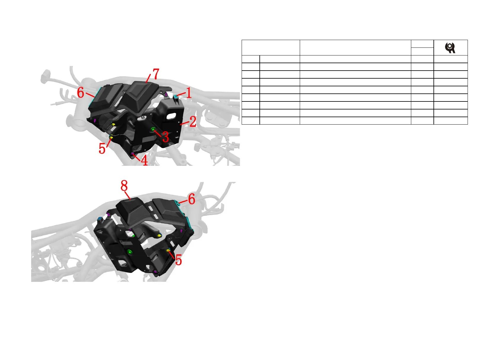
Electronic parts COMPONENT 2
Fig.2 FRAME&ELECTRONIC
COMPONENT
PROCEDURE:
●Front electrical device box
It is necessary to remove the engine, fluid control unit, flasher, carbon canister, etc. first.
Remove the bottom bolts (5) with a 4# hex, and remove the 7 pieces of swell nails (4).
Remove the electronic parts component from the frame, and remove the two pieces of Flanging bushing
buffer (3) and the 4 pieces of plywood (1).
●Front decorative cover
Remove the left front and right front decorative cover components from the frame.
Remove the pod glass strip (6) from the front of the decorative cover respectively.
CAUTION:
● This manual only roughly explains the disassembly steps, and replacing the front decorative cover and front
electrical device box is difficult, so it is recommended to go to a qualified aftermarket store for repairs.
 Loading...