Parameters 231
36.48 AL2 80 to 90% Percentage of samples recorded by amplitude logger 2
that fall between 80 and 90%.
0.00%
0.00…100.00% Amplitude logger 2 samples between 80 and 90%. 1 = 1%
36.49 AL2 over 90% Percentage of samples recorded by amplitude logger 2
that exceed 90%.
0.00%
0.00…100.00% Amplitude logger 2 samples over 90%. 1 = 1%
36.50 AL2 reset date The date on which amplitude logger 2 was last reset. 01/01/1980
1/1/1980...6/5/2159 Last reset date of amplitude logger 2. -
36.51 AL2 reset time The time at which amplitude logger 2 was last reset. 00:00:00
- Last reset time of amplitude logger 2. -
37
37 User load curve
Settings for user load curve.
See also section User load curve (page 63).
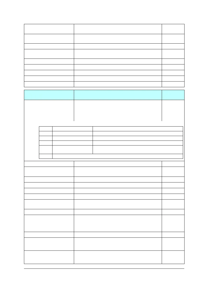
37.01 ULC output status
word
Displays the status of the monitored signal (37.02). The
status is shown only while the drive is running. (The status
word is independent of the actions and delays selected by
parameters 37.03, 37.04, 37.41 and 37.42.)
This parameter is read-only.
0000h
0000h…FFFFh Status of the monitored signal. 1 = 1
37.02 ULC supervision
signal
Selects the signal to be monitored. The function compares
the absolute value of the signal against the load curve.
Motor
torque %
Not selected No signal selected. Monitoring disabled. 0
Motor speed % 01.03 Motor speed %.1
Motor current % 01.08 Motor current % of motor nom.2
Motor torque % 01.10 Motor torque.3
Output power % of
motor nom
01.15 Output power % of motor nom.4
Other Source selection (see Terms and abbreviations). -
37.03 ULC overload actions Selects how the drive reacts if the absolute value of the
monitored signal stays continuously above the overload
curve for longer than the value of 37.41 ULC overload
timer.
Disabled
Disabled No warnings or fault generated. 0
Warning The drive generates an A8C1 ULC overload warning if the
signal has been continuously over the overload curve for a
time defined by parameter 37.41 ULC overload timer.
1
Fault The drive trips on 8002 ULC overload fault if the signal
has been continuously over the overload curve for a time
defined by parameter 37.41 ULC overload timer.
2
No. Name/Value Description Default
FbEq 16
Bit Name Description
0 Under load limit 1 = Signal lower than the underload curve.
1 Within load range 1 = Signal between the underload and overload curve.
2 Overload limit 1 = Signal higher than the overload curve.
3 Outside load limit 1 = Signal lower than the underload curve or higher than the
overload curve.
4…15 Reserved
ACS180 FW.book Page 231 Tuesday, March 9, 2021 2:25 PM

 Loading...


