Practical examples 105
Changing the rotation direction of the generator
General
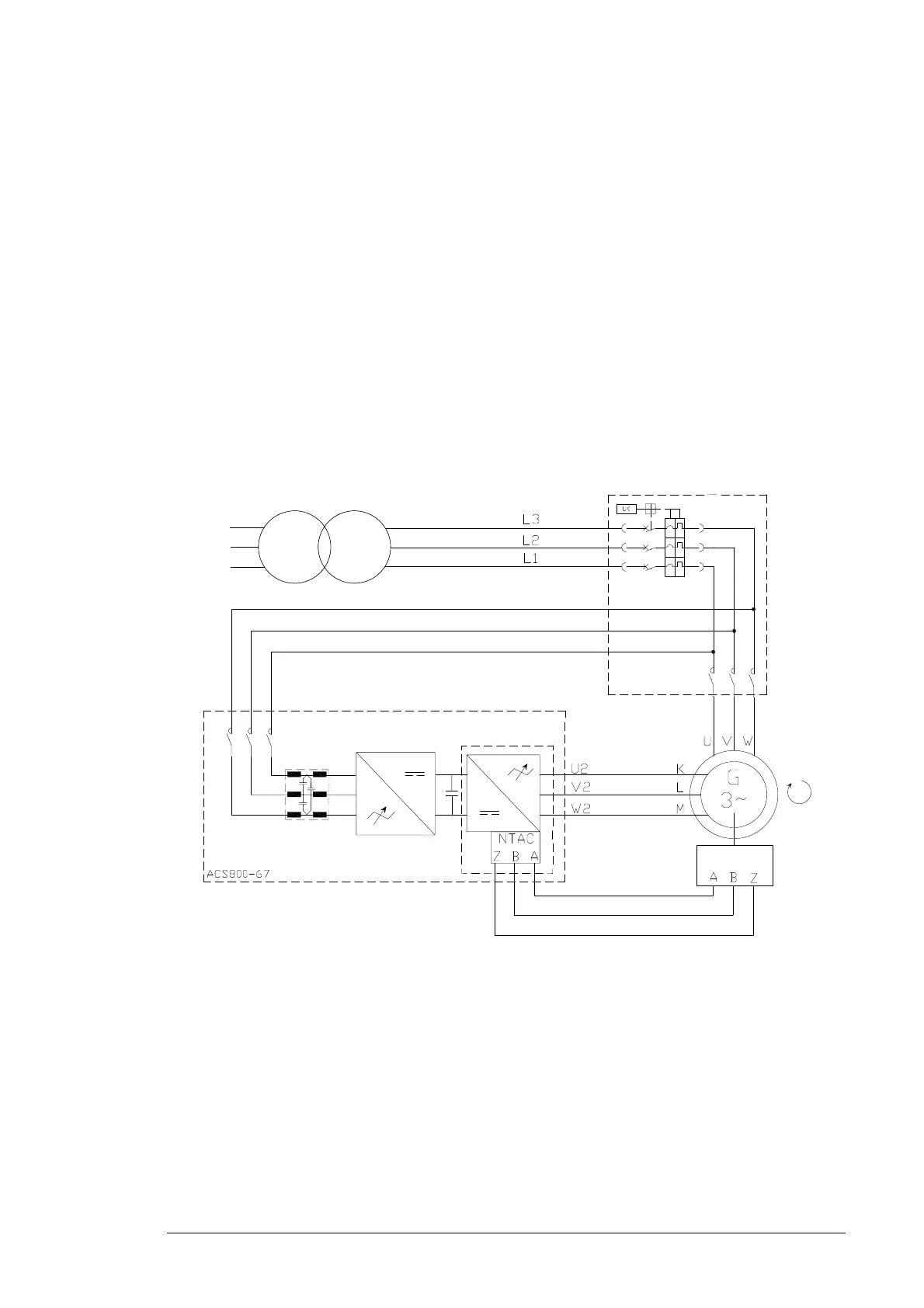
Terminal markings of the ABB generators for the stator (U, V, W) and rotor (K, L, M) are
based on IEC 60034-8. The terminal markings are arranged so that the clockwise rotation
is obtained when the alphabetical sequence of the letters (for example U1, V1, W1)
corresponds to the time sequence of the system phase voltages. The phase sequence of
the secondary winding (for example K, L, M) must correspond to the phase sequence of
the primary winding (for example U, V, W). In counterclockwise rotation the time sequence
of the system phase voltages are reversed by rearranging the grid cables (for example L2
and L3 in the case of 3-phase cabling). If the rotation direction of the generator is changed,
U, V, W are changed to V, U, W. Respectively K, L, M are changed to L, K, M. Grid
connections L1, L2, L3 connect to V, U, W and rotor connections U1, V1, W1 connect to L,
K, M in counterclockwise rotation.
Clockwise rotation at drive end (D end)

 Loading...


