Start-up with medium voltage stator 63
The control program checks the hardware connections automatically.
In a fault situation a fault message(s) is displayed:
WRONG ENCODER DIR
WRONG GRID DIR
GRID SYNC FAILED
WRONG ROTOR PHASING
Monitor the most important signals as explained below.
For the possible causes and remedies, see ACS800-67(LC) doubly-
fed induction generator control program firmware manual
[3AUA0000071689 (English)].
If everything is in order, the doubly-fed induction generator control
program continues to identify the generator magnetizing reactance.
It is useful to record important signals with the DriveWindow
monitoring PC tool.
01.01 MOTOR SPEED [rpm]
01.10 DC VOLTAGE [V]
01.11 MAINS VOLTAGE [V]
02.01 STATOR IS [RMS]
02.02 STATOR VOLTAGE [V]
02.06 ROTOR IR [RMS]
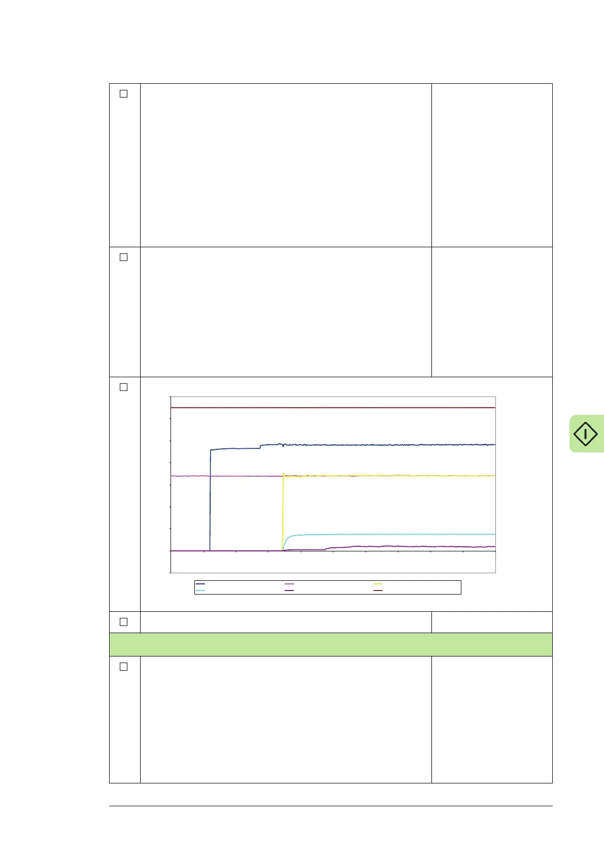
The figure below shows a typical start in local mode.
Stop the rotor-side converter with the DriveWindow STOP button.
Stator voltage synchronization test
Monitor the following rotor-side converter signals with DriveWindow
datalogger with 0.3 ms time level. Trigger condition must be 06.07
STATOR U FLUX and trig level 40 with rising edge.
06.03 ROTOR IU
06.04 ROTOR IY
06.07 STATOR U FLUX
06.05 GRID U FLUX
06.08 STATOR Y FLUX
06.06 GRID Y FLUX
06.03 ROTOR IU
06.04 ROTOR IY
06.07 STATOR U FLUX
06.05 GRID U FLUX
06.08 STATOR Y FLUX
06.06 GRID Y FLUX
N,
+* O1POQ +*-?O1POQ +*O1POQ
+*A-CPQ +*A-CPQ +*-E11 P)(*Q

 Loading...


