36 System description
Stator circuit connection to grid
The converter can control both breaker and contactor for connecting the generator stator
to the grid. The main difference between these configurations is that if the stator circuit is
equipped with a breaker, it allows disconnecting the stator from the grid even with a high
stator current. When the stator circuit is equipped with a contactor, disconnecting the
stator from the grid must be handled selectively. If the stator contactor is opened under
high current, it may be damaged.
Selective disconnection from the grid is handled so that any time the stator contactor is
commanded to open, instantaneous stator current is compared to the given limit. If stator
current is below the limit, the stator contactor is opened. Conversely, if stator current is
above the limit, the stator contactor is kept closed and the grid-side breaker (MCB1,
optional) is opened instead; the stator contactor is opened after a certain delay.
The hardware connection type for the grid connection is defined by parameter 16.20 GRID
CONNECT MODE. For the time schemes of the grid connection signals and operation of
digital inputs and outputs, see ACS800-67(LC) doubly-fed induction generator control
program firmware manual [3AUA0000071689 (English)]. The differences between the
configurations are presented below.
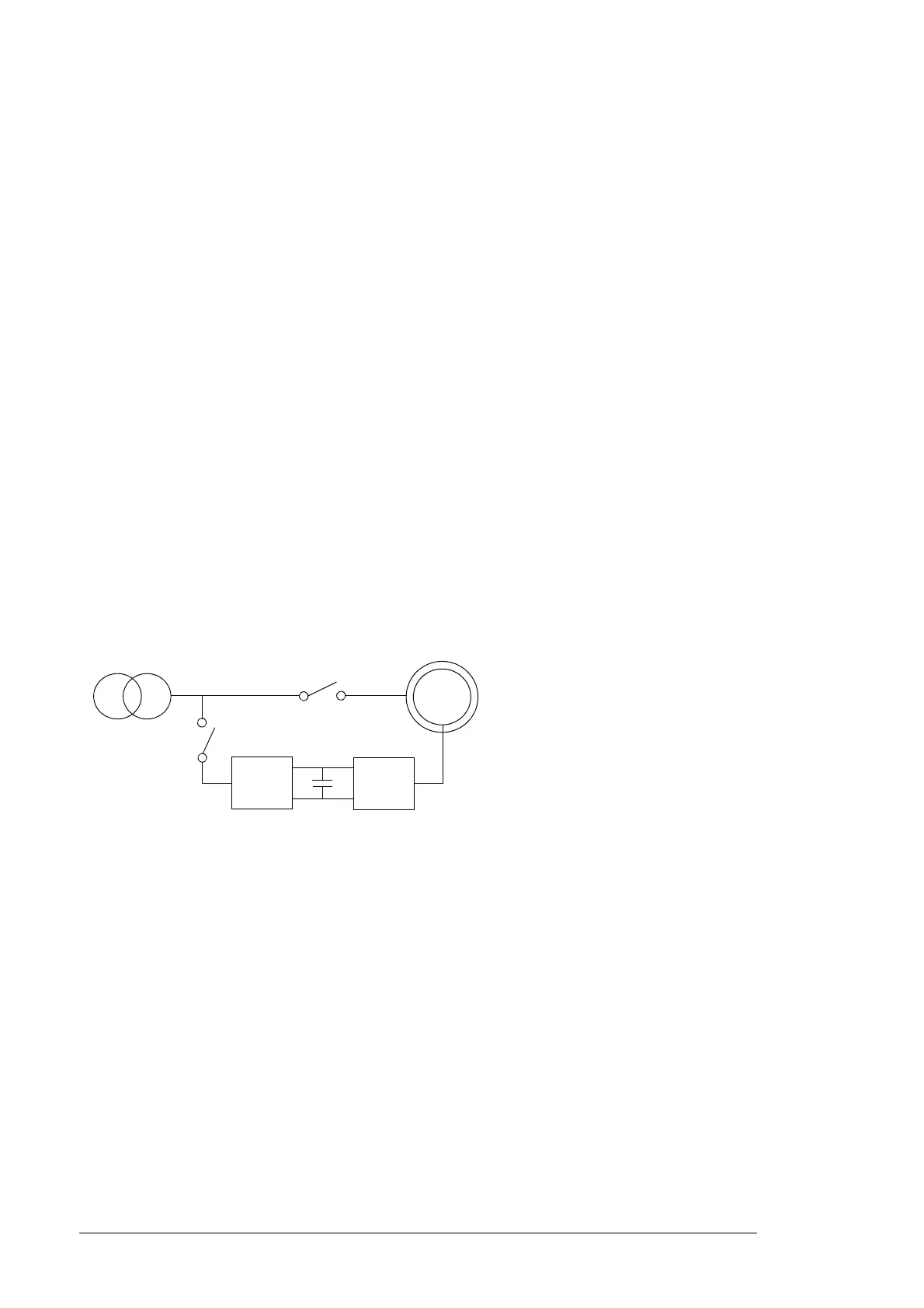
Stator breaker only (par. 16.20 GRID CONNECT MODE set to MCB3)
The configuration below is used when the stator is connected to the grid by the breaker
(MCB3) only.
ISU
INU
G
MCB3
MCB2
Turbine
transformer
MCB2 converter contactor
MCB3 stator breaker

 Loading...


