Tracing the source of warnings, limits and faults 115
Checking the phase sequence of grid-side converter
voltage measurement
NUIM board in use (grid-side converter control program IXXR72xx)
If an OVERCURRENT fault occurs during the start-up when the operation of the converter
is tested, or if the grid fault ride-through function fails, make the checks described in the
table below.
Action
Check the value of grid-side converter parameter 01.11 MAINS VOLTAGE. Refer to ACS800 IGBT
supply control program firmware manual [3AFE68315735 (English)].
If the voltage level is correct, the communication between NUIM board and DDCS channel 2 of the
grid-side converter control board is OK.
Check the phase sequence of the grid-side converter grid voltage measurement:
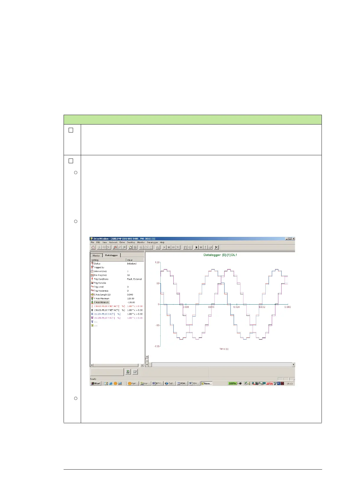
Monitor the following grid-side converter signals with DriveWindow Datalogger at 1 ms intervals:
138.02 FLUX X NET ACT (measured signal)
138.03 FLUX Y NET ACT (measured signal)
161.04 FLUX X ACT (converter actual signal)
161.05 FLUX Y ACT (converter actual signal).
Start the Datalogger and trigger it manually. Upload Datalogger information. An example view of the
Datalogger is shown below.
If signals 138.02 FLUX X NET ACT and 161.04 FLUX X ACT are in phase and signals 138.03 FLUX
Y NET ACT and 161.04 FLUX Y ACT are in phase, the measurement phase sequence is OK.
Note: If the signals are not in phase, check the grid voltage measurement cabling of the grid-side
converter measuring unit and correct the phase sequence. See the converter hardware manual.

 Loading...


