Practical examples 93
Normal start and stop sequence, ABB drives profile
An example of the control sequence is described below.
Datasets
The datasets used for transmitting and receiving actual signals and parameters are shown
in ACS800-67(LC) doubly-fed induction generator control program firmware manual
[3AUA0000071689 (English)].
Fieldbus signals
For signals used in the software interface with a specific fieldbus, refer to the software
interface specification delivered with the converter.
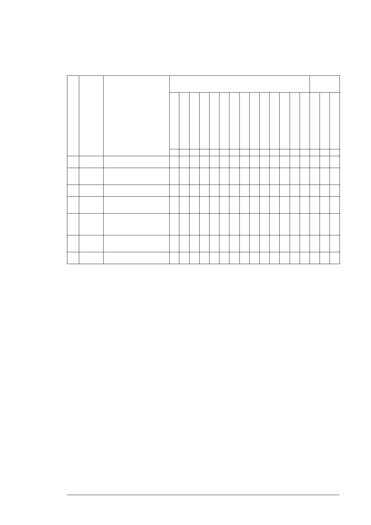
Step Command
/ end state
Description 8.10 CCU STATUS WORD bits after command 7.01 MAIN
CONTROL
WORD
ISU RDYREF
MCB internal trip
MCB ON
Low voltage for ride through
remote
torque reduction
alarm
crowbar triggered
-
OFF 2 N STA
tripped
rdyref
rdyrun
rdyon
RESET
RUN
ON
b13 b12 b11 b10 b9 b8 b7 b6 b5 b4 b3 b2 b1 b0 b7 b3 b0
1 RUN, ON
= 0
Device is at a standstill, no fault.00001000010001000
2 ON=1 DC bus is charged, ISU
contactor is closed and ISU
modulation is started.
10001000010001001
When speed is above SWITCH-
ON speed.
10001000010011001
3 RUN=1 INU is started, synchronised to
the grid and stator is connected
to the grid.
10101000010111011
4 RUN=0 Stator current is controlled to
zero, stator is disconnected from
the grid and INU modulation is
stopped.
10001000010011000
5 ON=0 ISU modulation is stopped, ISU
contactor is opened and DC bus
is discharged.
00001000010011000
6 When speed is below SWITCH-
OFF speed.
00001000010001000

 Loading...


