74 Start-up with medium voltage stator
Start in local control mode
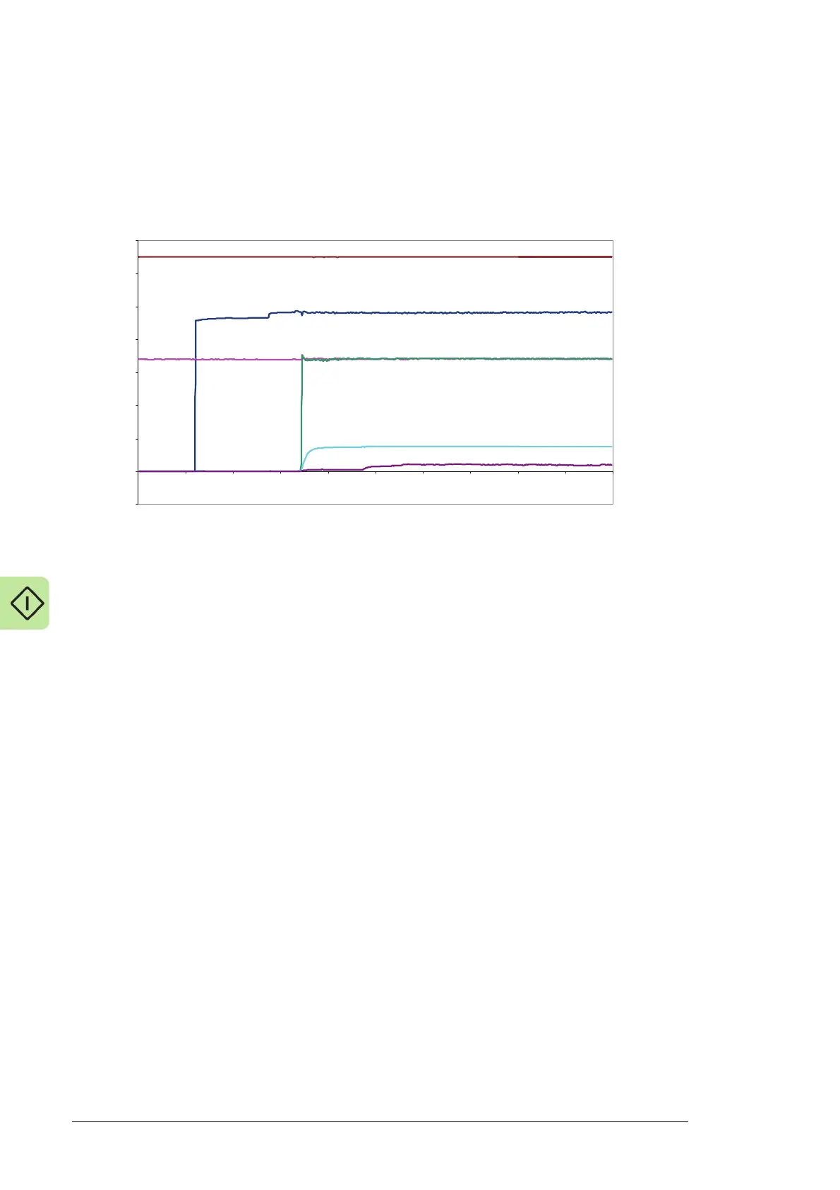
It is useful to record important signals with the DriveWindow PC tool when the wind turbine
converter is connected to the grid. The figure below represents a typical start in local
mode.
1. Grid-side converter is started and DC link charging begins. DC link voltage starts to
increase and auxiliary power is connected to the rotor-side converter. After these
actions, the converter signals can be monitored.
2. Grid-side converter charging is finished. Modulation of both converters starts. Stator
voltage increases near to the measured grid voltage.
3. DC voltage increases to its maximum if the rotor speed is near the lowest possible
start speed.
4. The converter software adjusts the stator voltage in order to minimise current
transients during grid connection.
5. Main circuit breaker is closed.
-200
0
200
400
600
800
1000
1200
1400
012345678910
1.01 MOTOR SPEED [rpm]
1.10 DC VOLTAGE [V]
1.11 MAINS VOLTAGE [V]
2.02 STATOR VOLTAGE [V]
2.06 ROTOR IR (RMS) [A]
2.01 STATOR IS (RMS) [A]

 Loading...


