Practical examples 83
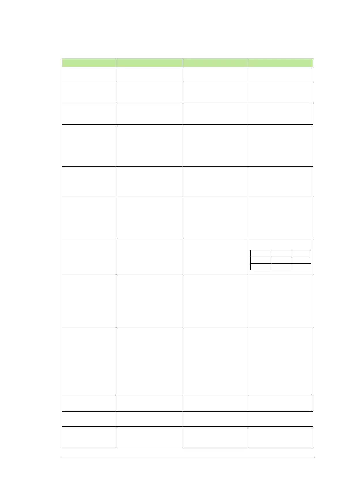
Parameters of parameter group 99
Parameter Description Source Description
99.02 MOTOR NOM
VOLTAGE
Defines the nominal
generator voltage.
Rated stator voltage in
data sheet
99.03 MOTOR NOM
CURRENT
Defines the nominal
generator stator-side
current.
Rated stator current in
data sheet
The value is for information
only. It is not used by the
firmware in any way.
99.04 MOTOR NOM
FREQ
Defines the nominal
generator frequency.
Rated stator (grid)
frequency in data sheet
The value is either 50 Hz
or 60 Hz depending on the
grid.
99.05 MOTOR NOM
SPEED
Defines the nominal
generator speed.
Defined in data sheet or
calculated estimate.
See separate instruction
below.
Used for the modeling of
the DFIG.
The speed of DFIG when
operating rotor short-
circuited with nominal
power.
99.06 MOTOR NOM
POWER
Defines the nominal
generator power.
Calculated value
See separate instruction
below.
Used for the scaling of the
torque reference.
Note: This is not the rated
power of the DFIG.
99.12 MOTOR NOM
COS FII
Defines the generator
power factor at nominal
loading point.
Must be equal to the value
on the generator data
sheet.
Power factor in data sheet The value is for information
only. It is not used by the
firmware in any way.
99.14 MOTOR SYNC
SPEED
Defines the synchronous
speed of the generator.
Select based on motor
pole pair and grid
frequency.
Select
99.15 MOTOR OPEN
CKT V
Defines the open-circuit
voltage of the rotor. That
is, rotor voltage without
load when nominal voltage
is connected to the stator
and the rotor is locked (U2
on the generator data
sheet).
Locked rotor voltage
in data sheet.
Transformation ratio
between the stator and the
rotor. Defined when rotor
shaft is mechanically
locked and nominal stator
voltage is fed to the stator
windings.
99.16 MOTOR NOM
IM
Defines the maximum limit
of the rotor current to avoid
generator overheating.
If the rotor current exceeds
the value of parameter
99.16, the capacitive
reactive power is ramped
down until the current has
decreased below the value
of the parameter 99.16.
The limit for rotor current
protection.
Select from the data sheet
• largest rotor current in
the calculated operation
points, or
• maximum rotor current
The maximum limit of the
rotor current defined by the
generator supplier.
99.21 Rs Defines the stator
resistance.
Stator resistance (R
s
) of
equivalent circuit
DFIG characteristics value
99.22 X1S Defines the stator leakage
reactance.
Stator leakage reactance
of equivalent circuit
DFIG characteristics value
99.23 X2S Defines the rotor leakage
reactance reduced to the
stator side.
Rotor leakage reactance
of equivalent circuit
DFIG characteristics value
50 Hz 60 Hz
4-p 1500 1800
6-p 1000 1200

 Loading...


