450 Fieldbus control through the embedded fieldbus interface (EFB)
State transition diagram
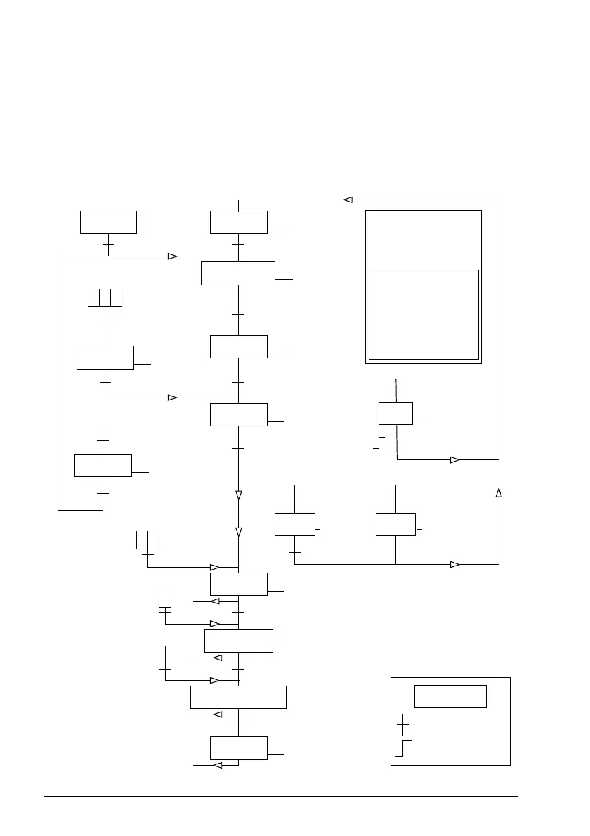
The diagram below shows the state transitions in the drive when the drive is using the
ABB Drives profile, and configured to follow the commands of the control word from
the embedded fieldbus interface. The upper case texts refer to the states which are
used in the tables representing the fieldbus Control and Status words. See sections
Control Word on page 447 and Status Word on page 449.
MAINS OFF
Power ON (CW Bit0=0)
(SW Bit6=1)
(SW Bit0=0)
from any state
(CW=xxxx x
1
xx xxxx x
110
)
(SW Bit1=1)
n(f)=0 / I=0
(SW Bit2=0)
ABCD
(CW Bit3=0)
operation
inhibited
OFF1
(CW Bit0=0)
(SW Bit1=0)
(SW Bit0=1)
(CW Bit3=1
and
SW Bit12=1)
CD
(CW Bit5=0)
(SW Bit2=1)
(SW Bit5=0)
from any state from any state
Emergency Stop
OFF3
(CW Bit2=0)
n(f)=0 / I=0
Emergency OFF
OFF2
(CW Bit1=0)
(SW Bit4=0)
B
BCD
(CW Bit4=0)
(CW=xxxx x
1
xx xxx
1 1111
)
(CW=xxxx x
1
xx xx
11 1111
)
D
(CW Bit6=0)
A
C
(CW=xxxx x
1
xx x
111 1111
)
(SW Bit8=1)
D
from any state
Fault
(SW Bit3=1)
(CW Bit7=1)
(CW=xxxx x
1
xx xxxx x
111
)
(CW=xxxx x
1
xx xxxx
1111
and SW Bit12=1)
CW = Control Word
SW = Status Word
n = Speed
I = Input Current
RFG = Ramp Function
Generator
f = Frequency
ABB Drives profile
SWITCH-ON
INHIBITED
NOT READY TO
SWITCH ON
READY TO
SWITCH ON
READY TO
OPERATE
OPERATION
INHIBITED
OFF1
ACTIVE
OPERATION
ENABLED
RFG: OUTPUT
ENABLED
RFG: ACCELERATOR
ENABLED
OPERATION
OFF2
ACTIVE
FAULT
OFF3
ACTIVE
STATE
condition
rising edge

 Loading...


