56 Standard programposi features
Digital input/output DIO1 is used as a frequency input, DIO2 as a frequency output.
The number of digital inputs/outputs are increased using FIO-xx I/O extensions. See
Programmable I/O extensions (page 56).
Settings
See parameter groups
• 10 Standard DI, RO
• 11 Standard DIO, FI, FO
Programmable relay outputs
The control unit has three relay outputs. The signal is indicated by the outputs are
selected using parameters.
Relay outputs are added using FIO-0x I/O extensions.
Settings
See parameter group 10 Standard DI, RO (page 128).
Programmable I/O extensions
Inputs and outputs are added using FIO-xx I/O extension modules. One to three
modules are mounted on the slots of the control unit.
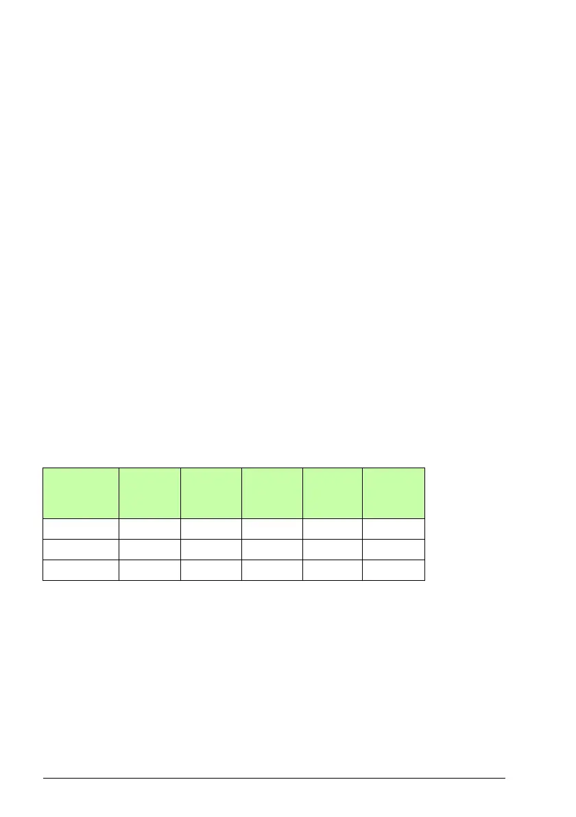
The table below shows the number of I/O on the control unit as well as optional
FIO-xx I/O extension modules.
Three I/O extension modules are activated and configured using parameter groups
14...16.
Note: Each configuration parameter group contains parameters that display the
values of the inputs on that particular extension module. These parameters are the
only way of utilizing the inputs on I/O extension modules as signal sources. To
connect to an input, choose the setting Other in the source selector parameter, then
specify the appropriate value parameter (and bit, for digital signals) in group 14, 15
or 16.
Location
Digital
inputs
(DI)
Digital
I/Os
(DIO)
Analog
inputs
(AI)
Analog
outputs
(AO)
Relay
outputs
(RO)
Control unit 7 2 2 2 3
FIO-01 -4--2
FIO-11 - 2 3 1 -

 Loading...


