Procedure
1. Prepare ferrules for the wires that are mentioned below. Refer to section 6.3.16.
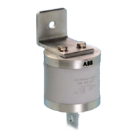
2. Connect the below listed wires from the outlets. Use the illustration above as a
reference:
Outlet
Wire Connect to terminal Terminal name
1 (A) 24V DC X4-1 +24Vdc CP1
(B) 0V DC X4-2 0Vdc gnd CP1
2 (C) 24V DC X5-1 +24Vdc CP2
(D) 0V DC X5-2 0Vdc gnd CP2
3 (E) 24V DC X6-1 +24Vdc CP3
(F)0V DC X6-2 0Vdc gnd CP3
4 (G) 24V DC X7-1 +24Vdc CP4
(H)0V DC X7-2 0Vdc gnd CP4
6.3.8 Connect the interlock and DC guard cables to the power cabinet
Preliminary requirements
• Interlock and DC guard
cables. Refer to section
12.13.9.
•
TOP
BOT
TOP
BOT
TOP
BOT
11
22
33
44
55
66
RJ45
TOP
BOT
TOP
BOT
TOP
BOT
11
22
33
44
55
66
RJ45
TOP
BOT
TOP
BOT
TOP
BOT
11
22
33
44
55
66
RJ45
TOP
BOT
TOP
BOT
TOP
BOT
11
22
33
44
55
66
RJ45
+24Vdc CP1
0V gnd CP1
+24Vdc CP2
0V gnd CP2
+24Vdc CP3
0V gnd CP3
+24Vdc CP4
0V gnd CP4
-X4 -X5
-X6 -X7
A B
C D
E F
G H
Installation
48 HVC 200/300/360-EN | 002
 Loading...