Outlet Wire Connect to terminal Terminal name
(R) DC guard signal X7-5 DC GUARD 4
(S) DC guard GND X7-6 DC GUARD 4 GND
(T) Ground wire or
shield mesh
X7 earthing terminal CP3 PE
6.3.9 Connect the Ethernet output cables to the power cabinet
Preliminary requirements
• Ethernet cables. Refer to
section 12.13.10.
•
Note:
• The maximum length of the ethernet cable is 100 meters.
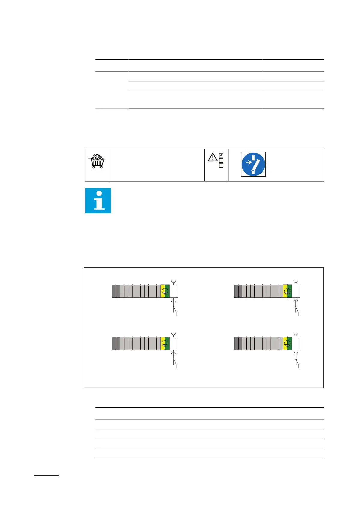
• The illustration shows the terminal blocks X4, X5, X6 and X7 on the
power cabinet and the connections that are in this section.
• For the specific connections, refer to the installation brief, the
installation drawing and the installation manuals of the devices
installed in the system you ordered.
• For information about the part numbers of the terminals, refer to
section 12.18.
Procedure
1. Connect the below listed wires from the outlets. Use the illustration above as a
reference:
Outlet
Wire Connect to terminal
1 (A) Ethernet output X4-X84
2 (B) Ethernet output X5-X85
3 (C) Ethernet output X6-X86
4 (D) Ethernet output X7-X87
TOP
BOT
TOP
BOT
TOP
BOT
11
22
33
44
55
66
RJ45
TOP
BOT
TOP
BOT
TOP
BOT
11
22
33
44
55
66
RJ45
TOP
BOT
TOP
BOT
TOP
BOT
11
22
33
44
55
66
RJ45
TOP
BOT
TOP
BOT
TOP
BOT
11
22
33
44
55
66
RJ45
-X4 -X5
-X6 -X7
A
B
D
C
Installation
HVC 200/300/360-EN | 002 51
 Loading...