Structure and function
2-10 3HDA000057A8519-001 Torch cleaner TC 2013
Assembly instructions
2.3.3 Replacement parts
The replacement parts include:
• Milling cutter (can be ordered individually)
• Replacement spacer plate for the clamping V-block (can be ordered individually)
• Release agent tank (1 litre silicone-free weld spatter release agent)
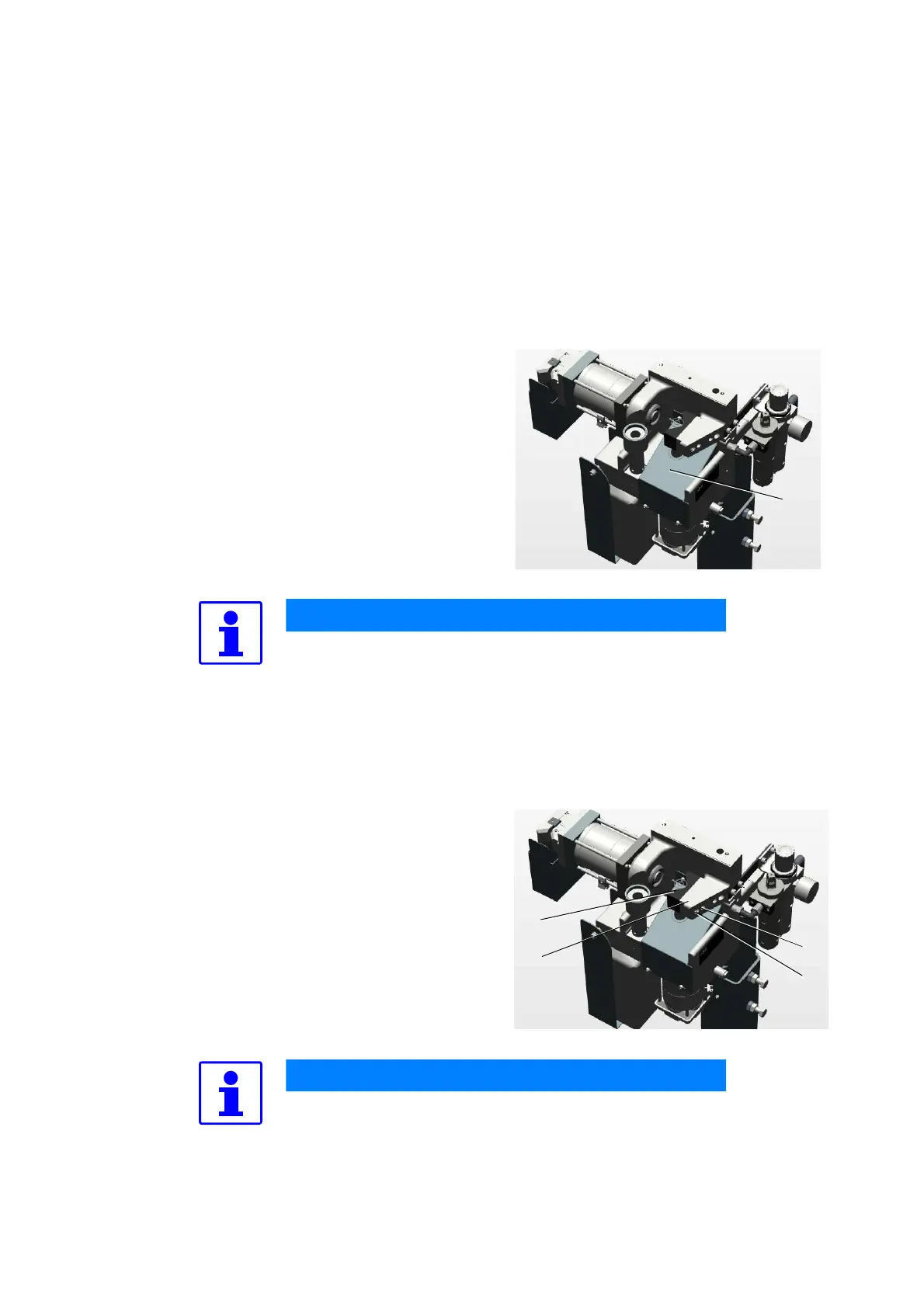
2.3.3.1 Replacing milling cutter
2.3.3.2 Replacing spacer plate
1. Remove protective cover (1).
2. On the milling cutter detach threaded pin M
5x6 and pull off milling cutter.
3. Put on new milling cutter and tighten with
threaded pin M 5x6.
4. Re-attach the protective cover (1) after
replacing the milling cutter.
At the factory the motor shaft is drilled approx. 1 mm
deep through the core hole in assembly of the first mill-
ing cutter in order to safely rule out axial migration of
the milling cutter.
1. The clamping V-block is screwed on with 2
cheese-head screws and pegged. Detach
screws (1) and pins (2).
2. Take off clamping V-block (3) and spacer
plate (4).
3. Select new spacer plate (see Table 2-1) and
screw back on clamping V-block and peg.
The center misalignment of the torch nozzle must then
be corrected in the robot program.
 Loading...