Home
Agilent Technologies
Multimeter
U1253B
Agilent Technologies U1253B User's And Service Guide
5
of 1
of 1 rating
221 pages
Give review
Manual
Specs
To Next Page
To Next Page
To Previous Page
To Previous Page
Loading...
106
U1253B User’s and Service Guide
4
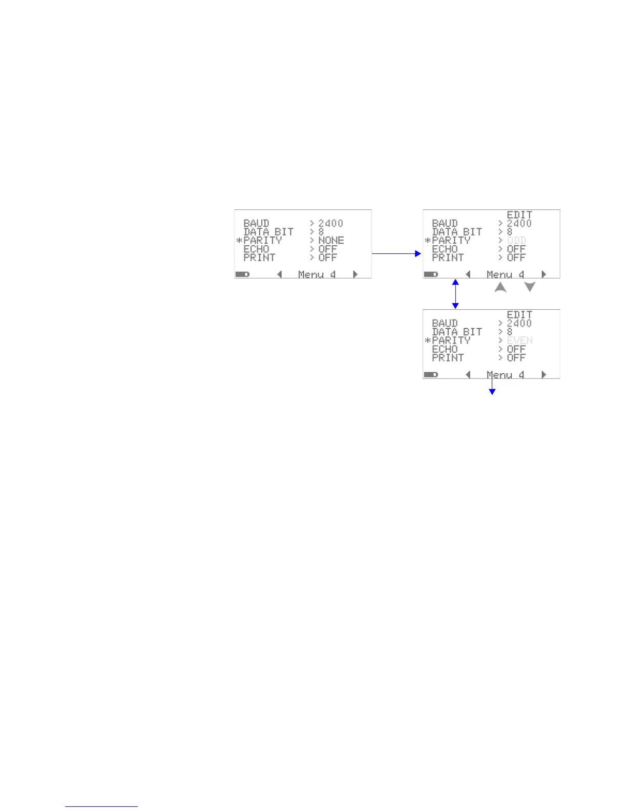
Changing the Default Settings
Setting parity check
The parity check f
or remote communication with a PC can
be set to eit
her NONE, ODD, or EVEN.
Figure 4-18
Parity check setup for remote control
to configure
Press Hz
to edit
Press
or
Press Hz to save
and exit
or press Esc
to exit without saving
129
131
Table of Contents
Default Chapter
2
Trademark Acknowledgements
2
Safety Symbols
3
General Safety Information
4
Environmental Conditions
7
In this Guide
10
Table of Contents
13
1 Getting Started Tutorial
26
Introducing the Agilent U1253B True RMS OLED Multimeter
26
Adjusting the Tilt-Stand
27
Figure 1-3 Tilt-Stand at Hanging Position
29
The Front Panel at a Glance
30
The Rotary Switch at a Glance
31
Table 1-1 Rotary Switch Description and Functions
31
The Keypad at a Glance
32
Figure 1-4 U1253B Keypad
32
Table 1-2 Keypad Descriptions and Functions
33
The Display at a Glance
35
Table 1-3 General Display Annunciators
35
Table 1-4 Primary Display Annunciators
36
Table 1-5 Secondary Display Annunciators
38
Table 1-6 Analog Bar Range and Counts
40
Selecting Display with the Shift Button
41
Table 1-7 Selecting Display with the Shift Button
41
Selecting Display with the Dual Button
43
Table 1-8 Selecting Display with the Dual Button
43
Selecting Display with the Hz Button
46
Table 1-9 Selecting Display with the Hz Button
46
The Terminals at a Glance
49
Figure 1-5 Connector Terminals
49
Table 1-10 Terminal Connections for Different Measurement
50
The Rear Panel at a Glance
51
Figure 1-6 Rear Panel of U1253B
51
2 Making Measurements
53
Measuring Voltage
54
Measuring AC Voltage
54
Figure 2-1 Measuring AC Voltage
55
Measuring DC Voltage
56
Figure 2-2 Measuring DC Voltage
56
Measuring Current
57
A and Ma Measurement
57
Μa and Ma Measurement
57
Figure 2-3 Measuring Μa and Ma Current
58
Percentage Scale of 4 Ma to 20 Ma
59
Table 2-1 Percentage Scale and Measurement Range
59
Figure 2-4 Measurement Scale of 4 Ma to 20 Ma
60
A (Ampere) Measurement
61
Figure 2-5 a (Ampere) Current Measurement
61
Frequency Counter
62
Figure 2-6 Measuring Frequency
63
Measuring Resistance, Conductance, and Testing Continuity
64
Figure 2-7 Type of Display When Smart
65
Figure 2-8 Measuring Resistance
66
Figure 2-9 Resistance, Audible Continuity, and Conductance
67
Table 2-2 Audible Continuity Measurement Range
68
Figure 2-10 Short Continuity and Open Continuity Test
69
Figure 2-11 Conductance Measurement
70
Testing Diodes
71
Figure 2-12 Measuring the Forward Bias of a Diode
72
Figure 2-13 Measuring the Reverse Bias of a Diode
73
Measuring Capacitance
74
Measuring Temperature
75
Figure 2-14 Surface Temperature Measurement
77
Alerts and Warning During Measurement
78
Voltage Alert
78
Input Warning
79
Figure 2-15 Input Terminal Warning
79
Charge Terminal Alert
80
Figure 2-16 Charge Terminal Alert
80
3 Functions and Features
82
Dynamic Recording
82
Figure 3-1 Dynamic Recording Mode Operation
83
Data Hold (Trigger Hold)
84
Figure 3-2 Data Hold Mode Operation
85
Refresh Hold
86
Figure 3-3 Refresh Hold Mode Operation
87
Null (Relative)
88
Figure 3-4 Null (Relative) Mode Operation
89
Decibel Display
90
Figure 3-5 Dbm Display Mode Operation
91
Figure 3-6 Dbv Display Mode Operation
92
Ms Peak Hold
93
Figure 3-7 1 Ms Peak Hold Mode Operation
94
Data Logging
95
Manual Logging
95
Figure 3-8 Manual (Hand) Logging Mode Operation
96
Figure 3-9 Full Log
96
Interval Logging
97
Figure 3-10 Interval (Time) Logging Mode Operation
98
Reviewing Logged Data
99
Figure 3-11 Log Review Mode Operation
100
Square Wave Output
101
Table 3-1 Available Frequencies for Square Wave Output
101
Figure 3-12 Frequency Adjustment for Square Wave Output
102
Figure 3-13 Duty Cycle Adjustment for Square Wave Output
103
Figure 3-14 Pulse Width Adjustment for Square Wave Output
104
Remote Communication
105
Figure 3-15 Cable Connection for Remote Communication
105
4 Changing the Default Settings
108
Selecting Setup Mode
108
Default Factory Settings and Available Setting Options
109
Table 4-1 Default Factory Settings and Available Setting Options for
109
Figure 4-1 Setup Menu Screens
112
Figure 4-2 Data Hold/Refresh Hold Setup
113
Setting Data Hold/Refresh Hold Mode
113
Figure 4-3 Data Logging Setup
114
Setting Data Logging Mode
114
Figure 4-4 Log Time Setup for Interval (Time) Logging
115
Figure 4-5 Decibel Measurement Setup
116
Setting Db Measurement
116
Figure 4-6 Setting up the Reference Impedance for Dbm Unit
117
Setting Reference Impedance for Dbm Measurement
117
Figure 4-7 Thermocouple Type Setup
118
Setting Temperature Unit
118
Setting Thermocouple Types
118
Figure 4-8 Temperature Unit Setup
119
Figure 4-9 Setting up Percentage Scale Readout
120
Setting Percentage Scale Readout
120
Figure 4-10 Choosing the Sound Used in Continuity Test
121
Sound Setting for Continuity Test
121
Figure 4-11 Minimum Frequency Setup
122
Setting Minimum Measurable Frequency
122
Figure 4-12 Beep Frequency Setup
123
Setting Beep Frequency
123
Setting Auto Power off Mode
124
Figure 4-13 Automatic Power Saving Setup
125
Figure 4-14 Power-On Backlight Setup
126
Setting Power-On Backlight Brightness Level
126
Figure 4-15 Power-On Melody Setup
127
Setting the Power-On Melody
127
Figure 4-16 Power-On Greeting Setup
128
Setting the Power-On Greeting Screen
128
Figure 4-17 Baud Rate Setup for Remote Control
129
Setting Baud Rate
129
Figure 4-18 Parity Check Setup for Remote Control
130
Setting Parity Check
130
Figure 4-19 Data Bits Setup for Remote Control
131
Setting Data Bits
131
Figure 4-20 Echo Mode Setup for Remote Control
132
Setting Echo Mode
132
Figure 4-21 Print Mode Setup for Remote Control
133
Setting Print Mode
133
Figure 4-22 Revision Number
134
Figure 4-23 Serial Number
134
Revision
134
Serial Number
134
Figure 4-24 Voltage Alert Setup
135
Voltage Alert
135
M-Initial
136
Table 4-2 Available Settings for M-Initial
136
Figure 4-25 Setting Initial Measurement Functions
137
Figure 4-26 Navigating between the Initial Functions Pages
138
Figure 4-27 Editing Initial Measurement Function/Range
138
Figure 4-28 Editing Initial Measurement Function/Range and Initial Output Values
139
Figure 4-29 Refresh Rate for Primary Display Readings
140
Smooth Refresh Rate
140
Figure 4-30 Resetting to Default Factory Settings
141
Returning to Default Factory Settings
141
Figure 4-31 Battery Type Selection
142
Setting the Battery Type
142
Figure 4-32 DC Filter
143
Setting the DC Filter
143
5 Maintenance
145
Introduction
146
General Maintenance
146
Battery Replacement
147
Figure 5-1 Rear Panel of the Agilent U1253B True RMS OLED
148
Charging Battery
149
Figure 5-2 Self-Testing Time Display
150
Table 5-1 Battery Voltage and Corresponding Percentage of Charg
150
Figure 5-3 Performing Self-Test
151
Table 5-2 Error Messages
152
Figure 5-4 Charging Mode
153
Figure 5-5 Fully Charged and in the Trickle State
153
Figure 5-6 Battery Charging Procedures
155
Fuse Checking Procedure
156
Figure 5-7 Fuse Checking Procedures
156
Table 5-3 U1253B Measurement Readings for Fuse Checking
157
Fuse Replacement
158
Table 5-4 Fuse Specifications
158
Figure 5-8 Fuse Replacement
159
Troubleshooting
160
Table 5-5 Basic Troubleshooting Procedures
160
6 Performance Tests and Calibration
161
Calibration Overview
162
Closed-Case Electronic Calibration
162
Agilent Technologies' Calibration Services
162
Calibration Interval
162
Other Recommendations for Calibration
163
Recommended Test Equipment
164
Table 6-1 Recommended Test Equipment
164
Basic Operating Tests
165
Testing the Display
165
Figure 6-1 Displaying All OLED Pixels
165
Current Terminals Test
166
Figure 6-2 Current Terminal Error Message
166
Charge Terminals Alert Test
167
Figure 6-3 Charge Terminal Error Message
167
Test Considerations
168
Input Connections
169
Performance Verification Tests
170
Table 6-2 Performance Verification Tests
171
Calibration Security
177
Unsecuring the Instrument for Calibration
177
Figure 6-4 Unsecuring the Instrument for Calibration
179
Changing Calibration Security Code
180
Figure 6-5 Changing the Calibration Security Code
181
Resetting the Security Code to Factory Default
182
Figure 6-6 Resetting Security Code to Factory Default
183
Adjustment Considerations
184
Valid Adjustment Reference Input Values
185
Table 6-3 Valid Adjustment Reference Input Values
185
Calibration from Front Panel
189
Calibration Process
189
Calibration Procedures
190
Figure 6-7 Typical Calibration Process Flow
192
Table 6-4 List of Calibration Items
193
Calibration Count
197
Calibration Error Codes
198
Table 6-5 Calibration Error Codes and Their Respective
198
7 Specifications
199
DC Specifications
200
AC Specifications
203
Table 7-2 Accuracy Specifications ± (% of Reading + Number of LSD) for True RMS AC Voltage
203
Table 7-3 Accuracy Specifications ± (% of Reading + Number of LSD) for True RMS AC Current
203
AC+DC Specifications
205
Table 7-4 Accuracy Specifications ± (% of Reading + Number of LSD) for AC+DC Voltage
205
Table 7-5 Accuracy Specifications
205
Temperature and Capacitance Specifications
207
Temperature Specifications
207
Table 7-6 Temperature Specifications
207
Capacitance Specifications
208
Table 7-7 Capacitance Specifications
208
Frequency Specifications
209
Frequency Sensitivity During Voltage Measurement
209
Table 7-8 Frequency Specifications
209
Table 7-9 Frequency Sensitivity and Trigger Level
209
Frequency Sensitivity During Current Measurement
210
Table 7-10 Sensitivity for Current Measurement
210
Duty Cycle [1] and Pulse Width [2]
211
Table 7-11 Accuracy for Duty Cycle
211
Table 7-12 Accuracy for Pulse Width
211
Frequency Counter Specifications
212
Table 7-13 Frequency Counter (Divide 1) Specifications
212
Table 7-14 Frequency Counter (Divide 100) Specifications
212
Peak Hold (Capturing Changes)
213
Square Wave Output
213
Table 7-15 Peak Hold Specification
213
Table 7-16 Square Wave Output Specifications
213
Operating Specifications
214
Table 7-17 Measurement Rate
214
Table 7-18 Input Impedance
215
General Specifications
216
Measurement Category
219
Measurement Category Definition
219
Other manuals for Agilent Technologies U1253B
User's Guide And Service Guide
225 pages
Quick Start Guide
13 pages
5
Based on 1 rating
Ask a question
Give review
Questions and Answers:
Need help?
Do you have a question about the Agilent Technologies U1253B and is the answer not in the manual?
Ask a question
Agilent Technologies U1253B Specifications
General
Brand
Agilent Technologies
Model
U1253B
Category
Multimeter
Language
English
Related product manuals
Agilent Technologies U1252B
191 pages
Agilent Technologies U1251A
169 pages
Agilent Technologies U1241B
89 pages
Agilent Technologies U1242B
89 pages
Agilent Technologies U1242A
85 pages
Agilent Technologies U1241A
85 pages
Agilent Technologies U1231A
133 pages
Agilent Technologies U3402A
127 pages
Agilent Technologies U3606A
288 pages
Agilent Technologies 3458A
372 pages
Agilent Technologies 34401A
242 pages
Agilent Technologies 34411A
144 pages

 Loading...


