Making Measurements 2
U1253B User’s and Service Guide 47
Testing Diodes
To test a diode, switch the circuit power off, and remove the
diode from the circuit. Then proceed as follows:
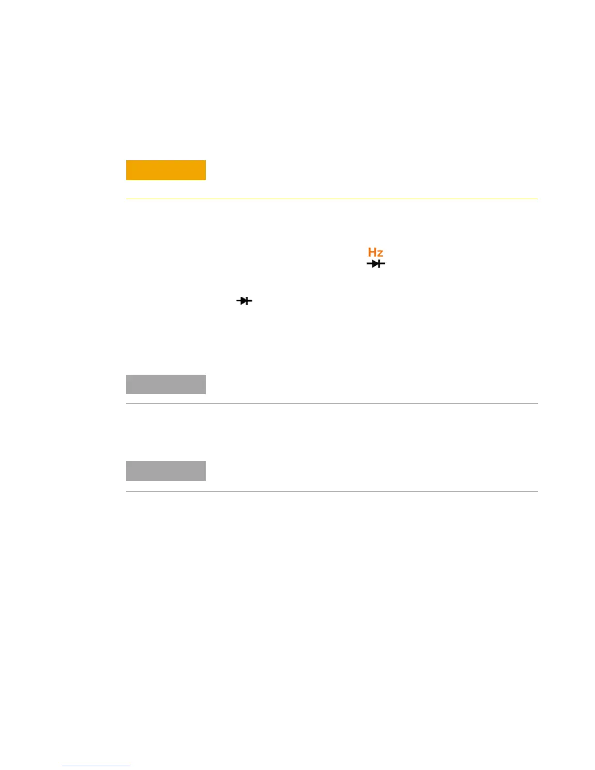
1 Set the rotary switch to . The default function is
diode measurement.
2 Connect the red and black test leads to input terminals
(red) and COM (black) respectively.
3 Connect the red test lead to the positive terminal (anode)
of the diode and the black test lead to the negative
terminal (cathode). Refer to Figure 2- 12 on page 48.
4 Read the display.
5 Reverse the probes and measure the voltage across the
diode again (refer to Figure 2- 13 on page 49). Assess the
diode according to the following guidelines:
• A diode is considered good if the multimeter displays
“OL” in reverse bias mode.
• A diode is considered shorted if the multimeter
displays approximately 0 V in both forward and reverse
bias modes, and the multimeter beeps continuously.
• A diode is considered open if the multimeter displays
“OL” in both forward and reverse bias modes.
Disconnect circuit power and discharge all high-voltage capacitors
before testing diodes to avoid damaging the multimeter.
The cathode of a diode is indicated with a band.
This multimeter can display diode forward bias of up to approximately 3.1
V. The forward bias of a typical diode is within the range of 0.3 V to 0.8 V.

 Loading...


