38 U1253B User’s and Service Guide
2 Making Measurements
Frequency Counter
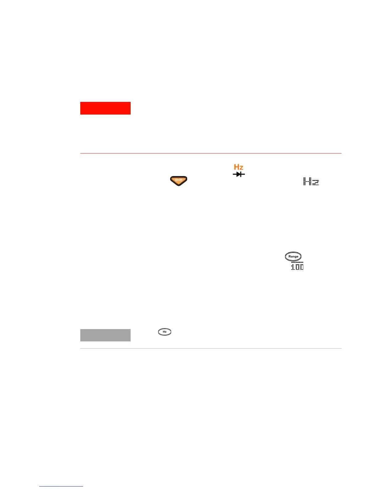
1 Set the rotary switch to .
2 Press to select the Frequency Counter ( )
function. The default input signal frequency is divided
by 1. This allows signals up to a maximum frequency of
985 kHz to be measured.
3 Connect the red and black test leads to input terminals
V (red) and COM (black) respectively (refer to Figure 2- 6 on
page 39).
4 Probe the test points and read the display.
5 If the reading is unstable or zero, press to select
division of input signal frequency by 100 ( will be
shown on the display). This accommodates a higher
frequency range of up to 20 MHz.
6 The signal is out of the U1253B frequency measurement
range of 20 MHz if the reading is still unstable after
Step 5.
• Use the frequency counter only for low voltage applications.
Never use the frequency counter on an AC power line system.
• For input more than 30 Vpp, you are required to use frequency
measurement mode available under the current or voltage
measurement instead of frequency counter.
Press to scroll through the pulse width (ms), duty cycle (%), and
frequency (Hz) measurements.

 Loading...


