40 U1253B User’s and Service Guide
2 Making Measurements
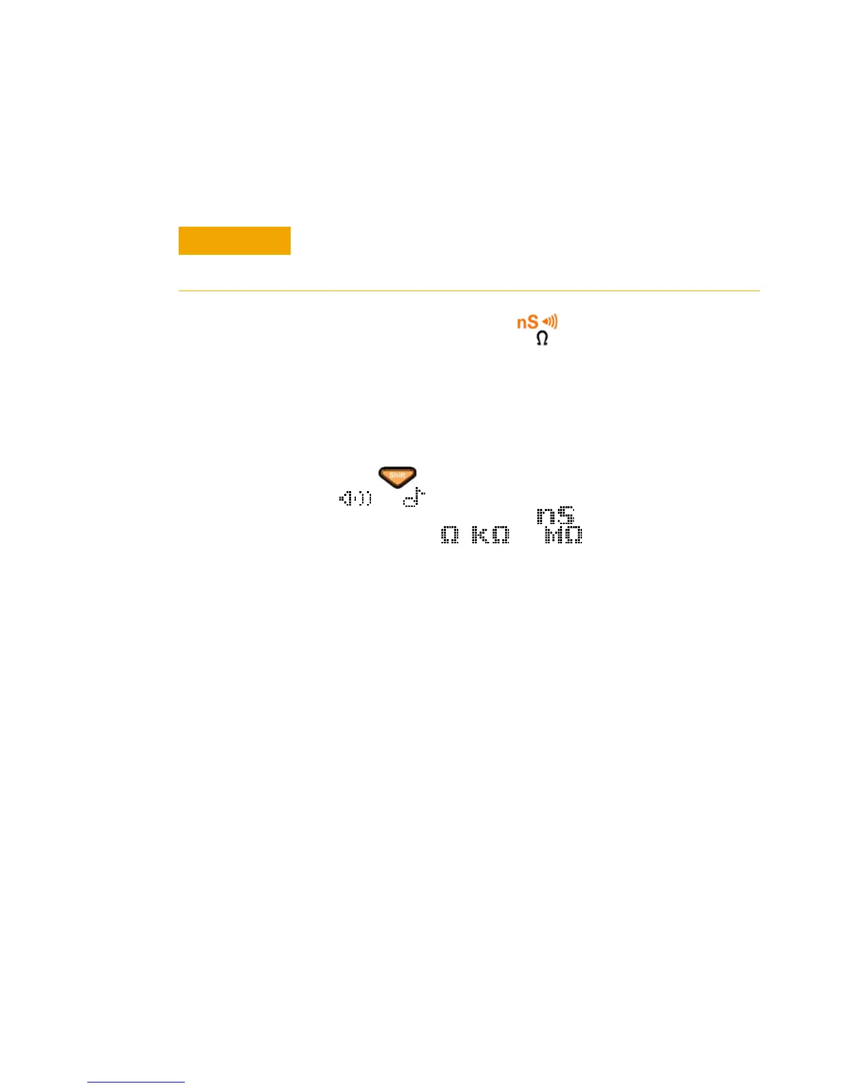
Measuring Resistance, Conductance, and Testing Continuity
1 Set the rotary switch to . The default function is
resistance measurement.
2 Connect the red and black test leads to input terminals
Ω (red) and COM (black) respectively (see Figure 2- 8 on
page 42).
3 Probe the test points (by shunting the resistor) and read
the display.
4 Press to scroll through audible continuity test
( or , depending on Setup configuration),
conductance measurement ( ), and resistance
measurement ( , , or ) as shown in
Figure 2- 9 on page 43.
Smart Ω
Using the offset compensation method, Smart Ω removes
unexpected DC voltages within instrument, at the input, or
the circuit being measured, which will add error to
resistance measurement. Besides, it also displays the bias
voltage or leakage current (calculated based on bias voltage
and corrected resistance value) on the secondary display.
With offset compensation method, the multimeter takes the
difference between two resistance measurements when two
different test currents are applied to determine any offset
voltage in the input circuitry. The resultant displayed
measurement corrects this offset, giving a more accurate
resistance measurement.
The Smart Ω is applicable for 500 Ω, 5 kΩ, 50 kΩ, and 500
kΩ resistance range only. The maximum correctable
offset/bias voltage is ±1.9 V for 500 Ω range and ±0.35 V for
5 kΩ, 50 kΩ, and 500 kΩ range.
Disconnect circuit power and discharge all high-voltage capacitors
before measuring resistance or conductance, or testing circuit
continuity, to avoid damaging the multimeter or the device under test.

 Loading...


