CE Conformity
D-4
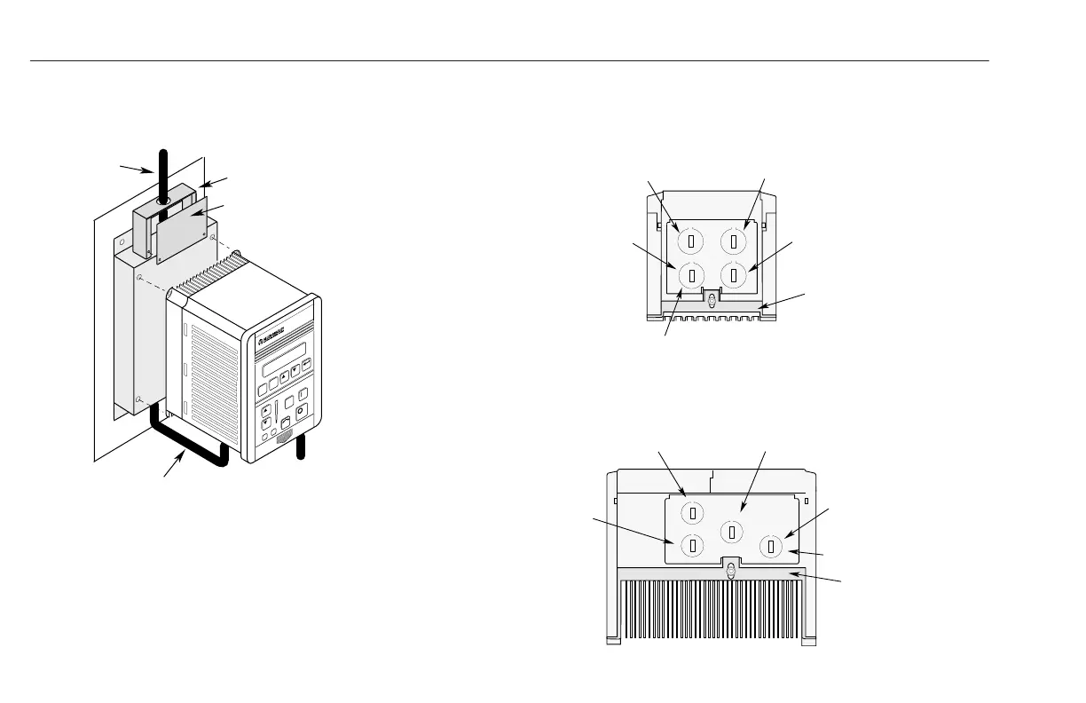
MECHANICAL CONFIGURATION
Figure D.2 Mechanical Configuration
Three-Phase
Input
➀
Terminal Block Cover Adapter
Terminal Block Cover
J
O
G
ESC
SEL
To Motor
➀
Cable Supplied with Filter
➀
➀
Input power (source to filter) and output power (filter to drive and
drive to motor) wiring must be in conduit or have shielding/armor with
equivalent attenuation. Shielding/armor must be bonded to the metal
conduit panel. See requirements 5 and 6 on page D-1 for details.
Figure D.3 Required Knockout Assignments
Frame A
(1305-AA02A, AA03A, AA04A)
Frames B and C
(1305-AA08A, AA12A, BA01A, BA02A, BA03A, BA04A, BA06A, BA09A)
Control I/O
Filter Input
Optional Brake
Motor Output
Grounding Bracket
Grounding Bracket
Filter Input
Control I/O
Additional Control
Motor Output
18.6 (0.73) - 4 Plcs.
18.6 (0.73) - 4 Plcs.
efesotomasyon.com - Allen Bradley,Rockwell,plc,servo,drive

 Loading...


