Installation/Wiring
2-13
Conduit
If metal conduit is preferred for cable distribution, the
following guidelines must be followed.
1. Drives are normally mounted in cabinets and ground
connections are made at a common ground point in the
cabinet. If the conduit is connected to the motor junction
box and at the drive end, no further conduit connections are
necessary.
2. No more than three sets of motor leads can be routed
through a single conduit. This will minimize “cross talk”
that could reduce the effectiveness of the noise reduction
methods described. If more than three drive/motor
connections per conduit are required, shielded cable as
described above must be used. If practical, each conduit
should contain only one set of motor leads.
ATTENTION: To avoid a possible shock hazard
caused by induced voltages, unused wires in the
conduit must be grounded at both ends. For the
same reason, if a drive sharing a conduit is being
serviced or installed, all drives using this conduit
should be disabled. This will eliminate the
possible shock hazard from “cross coupled” drive
motor leads.
!
Motor Lead Lengths
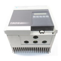
Installations with long cable lengths between the 1305 drive
and motor may require the use of an output reactor or
Terminator. The following guidelines allow for selection of the
appropriate drive HP rating (and output reactor or Terminator,
if required) to work with an existing motor, and provide
motor-lead length solutions for new installations.
Voltage doubling at motor terminals, known as reflected wave
phenomenon, standing wave or transmission line effect, can
occur when using long motor cables with drives. Long motor
cables can cause capacitive charging current in excess of the
rating of a smaller drive. To ensure proper installation, follow
the guidelines provided.
All cabling and distances are based on using 14 AWG,
4-conductor type cabling.
In general, motors designed and built without phase separating
insulation paper between motor windings should be classified
as 1000V
P-P insulation design.
Section A: No Output Reactor or Terminator
Table 2.D lists the maximum cable lengths permitted when
applying a 460V, 1305 drive to a 460V motor for motor
insulation ratings of 1000V, 1200V, and 1600V without an
output reactor or Terminator. Shielded and unshielded
maximum cable lengths also are listed. Tables are based on
operation at nominal line condition (480V).
efesotomasyon.com - Allen Bradley,Rockwell,plc,servo,drive

 Loading...


