J
O
G
ESC
SEL
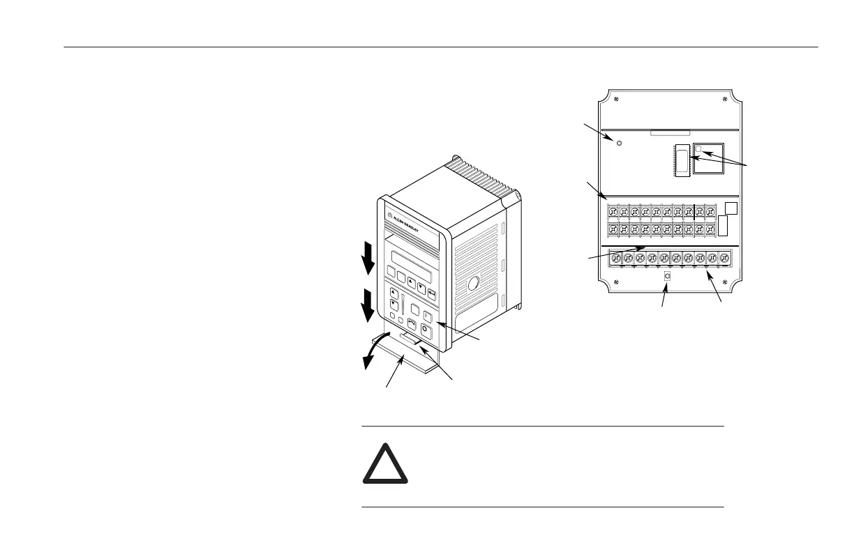
Retaining Lever
TB1
Power Terminal
Block
TB2
Control Terminal
Block
Firmware
Revision
Level
DC Bus Charge
Indicator
Drive with HIM Removed
Serial
Number
LED Fault
Indicator
HIM – See back for
Series Letter and
Firmware Revision Level
Hinged Cover
1 23456
9
10
87
11 12 13 14 15 16 17 18 19 20
ATTENTION: Proceed with caution. A DC Bus
Voltage may be present at the Power Terminal
Block (TB1) even when power is removed from
the drive.
!
Installation/Wiring
2-3
TERMINAL BLOCK ACCESS
To access the power and control terminal
blocks, perform the following procedure:
1. Remove power from the drive.
2. Lower the hinged panel located below the
HIM or blank front panel.
3. For drives equipped with a blank front
panel, slide the panel downward and
remove it from the drive. Skip to Step 5.
4. For drives equipped with a HIM, press the
retaining lever directly beneath the HIM
and slide the HIM downward to remove it
from drive.
5. Remove the drive front cover by grasping
the upper corners of the cover and pulling
at a 90-degree angle to the drive. Lift the
cover off.
Figure 2.3 Terminal Block Access
efesotomasyon.com - Allen Bradley,Rockwell,plc,servo,drive

 Loading...


