122 Rockwell Automation Publication 1734-UM013N-EN-P - September 2017
Chapter 6 Configure the Module for a SmartGuard Controller
6. Double-click Test Output Points to edit their configuration.
7. Click Apply and OK.
Configure Digital Safety Outputs
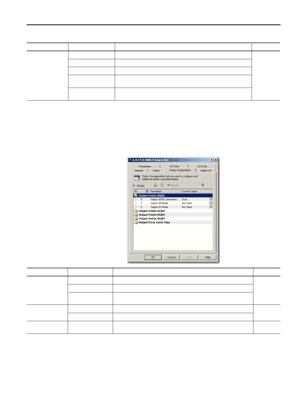
1. To display the parameters for editing, double-click each group of Outputs
Points.
Parameter Name Value Description Default
Test Output Mode Not Used An external device is not connected. Not Used
Standard The output is connected to a standard device.
Pulse Test A contact output device is connected. Use in combination with a safety input.
Power Supply The power supply of a Safety Sensor is connected. The voltage that is supplied to I/O power (V, G)
is output from the test output terminal.
Muting Lamp Output
(Terminal T1 or T3 only)
An indicator is connected and turned ON to detect broken lines in an external indicator.
Parameter Name Value Description Default
Output Point Mode Not Used An external output device is not connected. Not Used
Safety When the output is ON, the test pulse is not output (remains ON).
Safety Pulse Test When you use this function, short-circuits between output signal lines and the power supply
(positive side) and short-circuits between output signal lines can be detected.
Output Point Operation
Type
Single Channel Use as single channel. Dual-channel
Dual-channel Use as dual-channel. When both channels are normal, outputs can be turned ON.
Safety Output Error Latch
Time
0…65,530 ms
(in 10 ms increments)
Safety output errors are latched for this time. 1000 ms
 Loading...


