98 Rockwell Automation Publication 1734-UM013N-EN-P - September 2017
Chapter 5 Configure the Module in a GuardLogix Controller System
4. In the Output Error Latch Time field, enter the time that the module
holds an error to make sure that the controller can detect it (0…65,530 ms,
in increments of 10 ms - default 1000 ms).
This action provides more accurate diagnostics. The purpose for latching
output errors is to make sure that intermittent faults that can exist only for
a few milliseconds are latched long enough for the controller to read. The
amount of time to latch the errors is based on the RPI, the safety task
watchdog, and other application-specific variables.
5. Click Apply.
Add and Configure Safety
Analog Input Modules
To include a POINT Guard safety analog input module in the project, you add
the module to the POINT I/O™ Chassis, configure the general properties of the
module, and configure the analog inputs as described in the following sections.
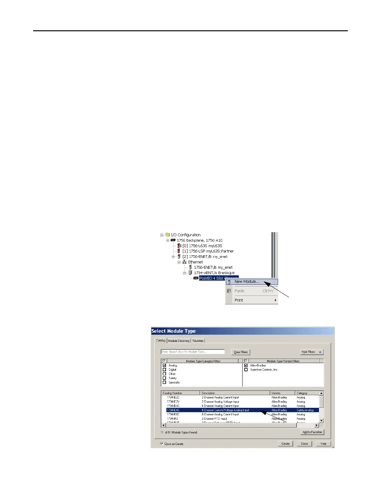
Add the Safety Analog Input Module
Follow these steps to add the POINT Guard I/O safety analog input module.
1. Right-click the POINT I/O Chassis and choose New Module.
2. From the Select Module dialog box, select an analog input module and
click Create.
 Loading...


