Rockwell Automation Publication 1734-UM013N-EN-P - September 2017 51
Guidelines for Placing Power Supplies and Modules in a System Chapter 3
Placing Series A Digital and
Analog Modules
Always install modules in accordance with their specified operating temperature
ratings, as listed in Appendix
, and provide a minimum of 5.08 cm (2 in.)
clearance above the modules.
• Limit ambient temperature operation to 40 °C (104°F) if Series A POINT
Guard I/O modules are used without 1734-CTM spacer modules.
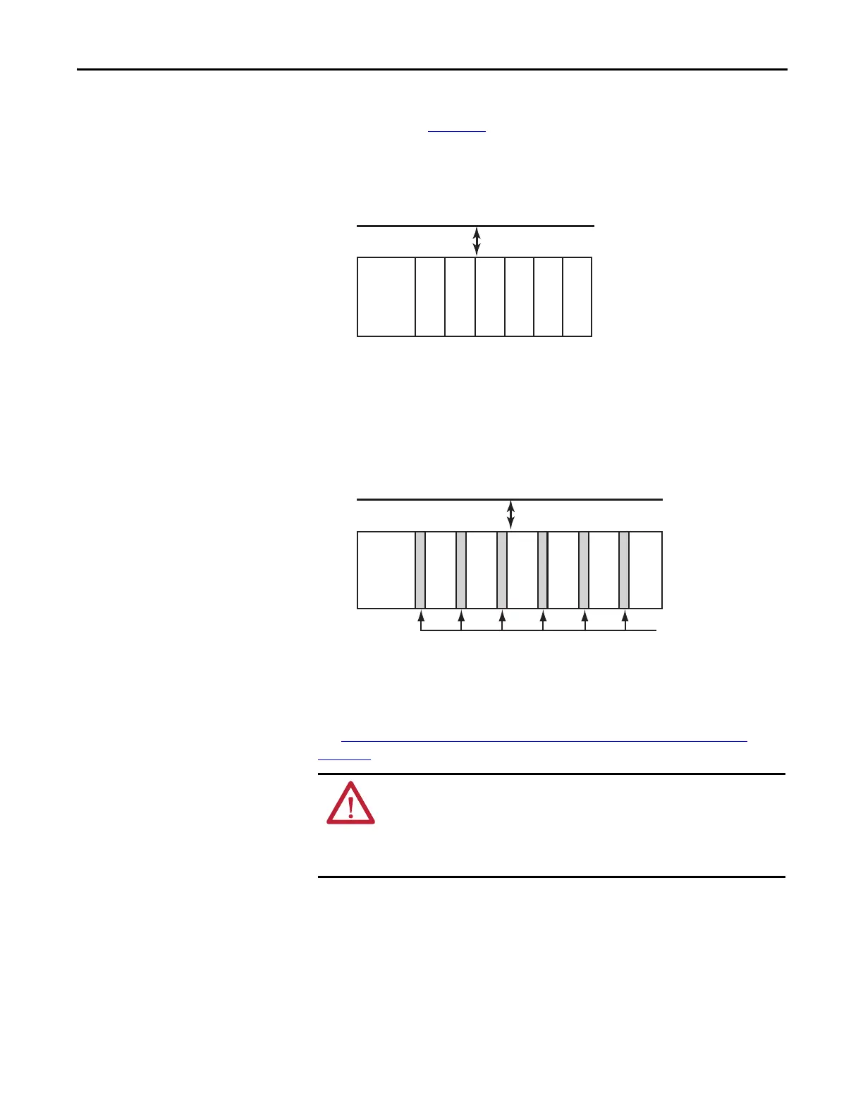
Figure 22 - Placing Series A Digital Modules for up to 40 °C (104 °F) Operation
• In any system where you have any Series A POINT Guard I/O modules,
use a 1734-CTM spacer between every POINT Guard I/O module with
ambient operation between 40 °C (104 °F) and 55 °C (131 °F).
Insert a 1734-CTM module next to each standard I/O module (gray) if
the thermal dissipation specification of that module is more than 1 W.
Figure 23 - Placing Series A Digital and Analog Modules for Operation from
40 °C (104 °F)…55°C (131°F) max.
• When using Series A POINT Guard I/O modules in your system limit the
power supply to 24V DC maximum, to limit the Series A POINT
Guard I/O thermal dissipation of the module.
See System Temperature Derating When a 1734-IE4S Module Is Used
on
page 198 for more information.
ATTENTION: Vertical orientation requires careful attention to design details
and panel layout so that all modules in the stack must operate within their
rated operating temperature range.
For Vertical installations, be sure that 1734-CTM spacer modules are installed next
to any Series A POINT Guard IO modules operating above 40 °C (104 °F) ambient.
1734-AENT
1734-IB8S/A
1734-IB8S/A
1734-OB8S/A
1734-IE4S/A
1734-IE4S/A
1734-IE4S/A
5.08 cm (2 in.)
1734-AENT
1734-IB8S/A
1734-IB8S/A
1734-OB8S/A
1734-IE4S/A
1734-IE4S/A
1734-IE4S/A
1734-CTM
5.08 cm (2 in.)
 Loading...


