EasyManua.ls Logo

Allen-Bradley 1734-OB8S User Manual

Allen-Bradley 1734-OB8S
235 pages
To Next Page IconTo Next Page
To Previous Page IconTo Previous Page
Page #150 background imageLoading...
Page #150 background image
150 Rockwell Automation Publication 1734-UM013N-EN-P - September 2017
Chapter 8 Replacing POINT Guard I/O Modules
The following, simplified example shows Guard I/O™ modules on a DeviceNet
network. Your products can differ, but the function is the same.
Manually Setting the Safety
Network Number
The previous examples showed how the SNN is used to provide safety-
connection integrity after the system is operational. But the SNN is also used to
provide integrity on the initial download to the POINT Guard I/O module.
If a safety signature exists, then the POINT Guard I/O module must have a
proper SNN/node number identification that matches the module within the
safety controller project, before it can receive its configuration. And to keep
integrity, the SNN setting of the module is required to be a manual action. This
manual action is to use the ‘set’ function on an out-of-box POINT Guard I/O
module.
EXAMPLE
The DeviceNet network supports 64 node numbers, so if you have 100 devices on multiple
DeviceNet networks, there are at least 36 duplicate node numbers being used. Even though the
duplicate nodes are on separate DeviceNet networks, it must still be considered in a safety
system.
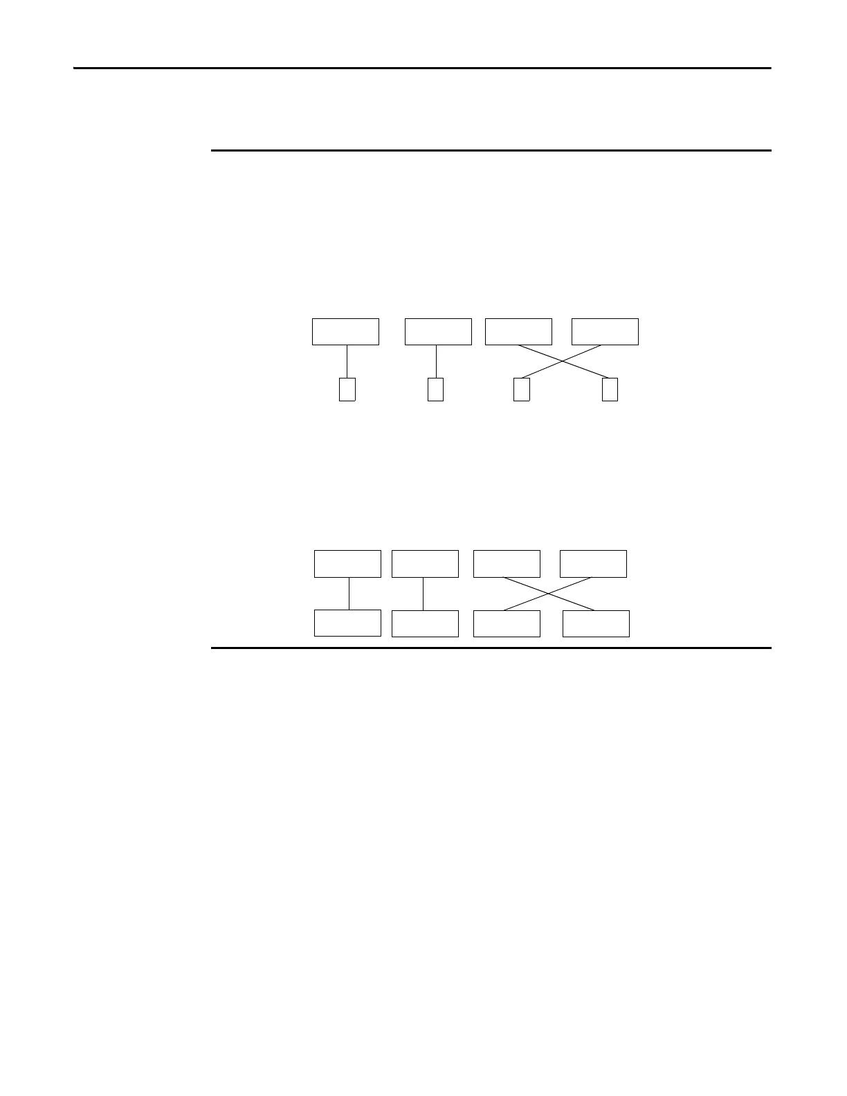
In this example, the DNB scanner #1 is connected to node 5. The DNB scanner #2 is connected to
another node 5. If the cables get inadvertently crossed, the scanners can be communicating with
the incorrect node 5.
Crossed Cables
This crossed-cable scenario is unacceptable for a safety system. The SNN provides unique
identification of every safety device. In this next example, all devices that are connected to DNB
scanner #1 have an SNN of 100. All devices that are connected to DNB scanner #2 have an SNN of
101. If the cables get inadvertently crossed, the node connected to DNB scanner #1 changes from
100/5 to 101/5. The node that is connected to DNB scanner #2 changes from 101/5 to 100/5.
Therefore, the safety connections are not made if the cables get crossed.
Connections Not Made
DNB #1 DNB #2 DNB #1 DNB #2
5555
DNB #1 DNB #2 DNB #1 DNB #2
5
SNN 100
5
SNN 101
5
SNN 100
5
SNN 101
Connections not
made.

Table of Contents

Other manuals for Allen-Bradley 1734-OB8S

Question and Answer IconNeed help?

Do you have a question about the Allen-Bradley 1734-OB8S and is the answer not in the manual?

Allen-Bradley 1734-OB8S Specifications

General IconGeneral
ManufacturerAllen-Bradley
Product TypeOutput Module
Output TypeSourcing
Number of Outputs8
Voltage Category24V DC
Communication InterfacePOINTBus
Operating Temperature-20 to 60 °C
Housing MaterialPlastic
Module TypeDigital Output
Isolation Voltage50V
Operating Voltage20.4-26.4V DC
Current Output0.5A per point, 4A per module

Summary

Point Guard I/O Safety Modules User Manual

User Manual

The primary manual for Point Guard I/O Safety Modules.

Important User Information

Key Safety Precautions

Essential safety warnings and instructions for using the modules.

Chapter 1 POINT Guard I/O Overview

Understand Suitability for Use

Guidance on determining if the product is suitable for a specific application.

Safety Precautions

Essential precautions to ensure proper and safe operation of the modules.

Chapter 2 Safety Inputs, Safety Outputs, and Safety Data

Safe States

Defines the safe states for digital and analog POINT Guard I/O modules.

Safety Inputs (1734-IB8S)

Details on using safety digital inputs with the 1734-IB8S module.

Safety Analog Inputs (1734-IE4S)

Information on configuring and using safety analog inputs.

Safety Outputs (1734-OB8S and 1734-OBV2S)

Details on configuring and using safety digital outputs.

Chapter 4 Install the Module

Precautions

Important precautions to follow during module installation.

Chapter 5 Configure the Module in a GuardLogix Controller System

Set up the Module

Initial steps to set up the module using Logix Designer.

Add and Configure Safety Digital Output Modules

Steps to add and configure safety digital output modules.

Configure Safety Connections

Procedure to configure safety input connections.

Add and Configure Safety Analog Input Modules

Steps to add and configure safety analog input modules.

Configure the Safety Analog Input Channel Operation

Details on configuring analog input channel operations.

Save and Download the Module Configuration

Recommended steps to save and download module configuration.

Add and Configure Safety Digital Input Modules

Steps to add and configure safety digital input modules.

Configure Tachometer Operation

Steps to configure the module for tachometer operation.

Chapter 6 Configure the Module for a SmartGuard Controller

Configure the POINT Guard I/O Modules

Steps for configuring POINT Guard I/O modules.

Chapter 7 Configuring Safety Connections between a GuardLogix Controller and POINT Guard I/O Modules on a DeviceNet Network

Verify Your DeviceNet Safety Configuration

Steps to verify the DeviceNet safety configuration.

Chapter 8 Replacing POINT Guard I/O Modules

Replace a Module in a GuardLogix System on an EtherNet/IP Network

Procedure for replacing modules in an EtherNet/IP system.

Appendix B Get I/O Diagnostic Status from Modules in Logix Systems

Message Instructions

Using message instructions to get diagnostic status.

Appendix C Specifications

Safety Digital Input Module Specifications

Specific safety digital input module specifications.

Safety Analog Input Module Specifications

Specific safety analog input module specifications.

Safety Digital Output Module Specifications

Specific safety digital output module specifications.

Related product manuals