Rockwell Automation Publication 1734-UM013N-EN-P - September 2017 97
Configure the Module in a GuardLogix Controller System Chapter 5
6. Click OK again to apply your changes.
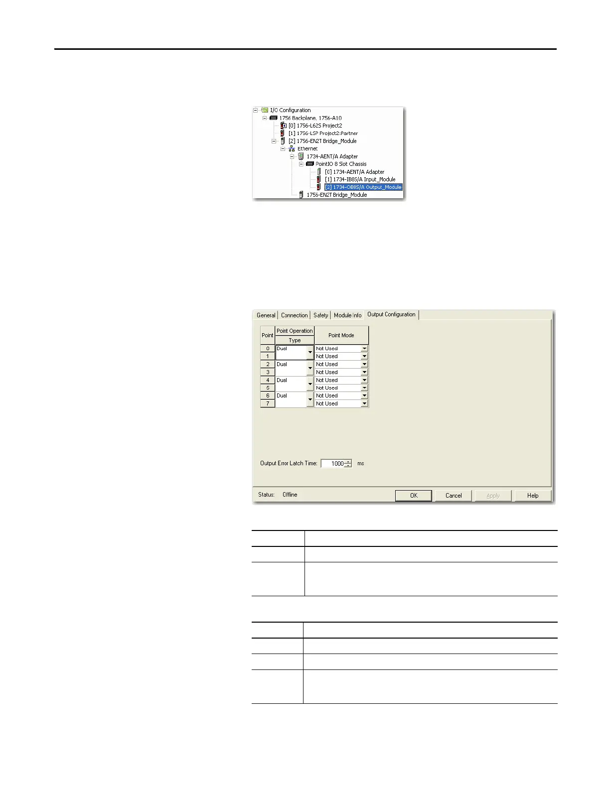
The I/O Configuration tree displays the output module.
Configure the Safety Digital Outputs
To configure the safety digital outputs, follow this procedure.
1. From the Module Properties dialog box, click the Output Configuration
tab.
2. Assign the Point Operation Type.
3. Assign the Point Mode.
Choose Description
Single The output is treated as one channel.
Dual (default) The POINT Guard I/O module treats the outputs as a pair. It always sets them HI or LO as a
matched pair. Safety logic must set both of these outputs ON or OFF simultaneously or the
module declares a channel fault.
Choose Description
Not Used The output is disabled.
Safety The output point is enabled and does not perform a pulse test on the output.
Safety Pulse
Te st
The output point is enabled and performs a pulse test on the output. When the output is
energized, the output pulses low briefly. The pulse test detects whether the output is
functioning properly.
 Loading...


