80 Rockwell Automation Publication 1734-UM013N-EN-P - September 2017
Chapter 5 Configure the Module in a GuardLogix Controller System
Add and Configure the
Ethernet Bridge
Follow this procedure to add and configure the Ethernet bridge. In this example,
we use a 1756 GuardLogix controller.
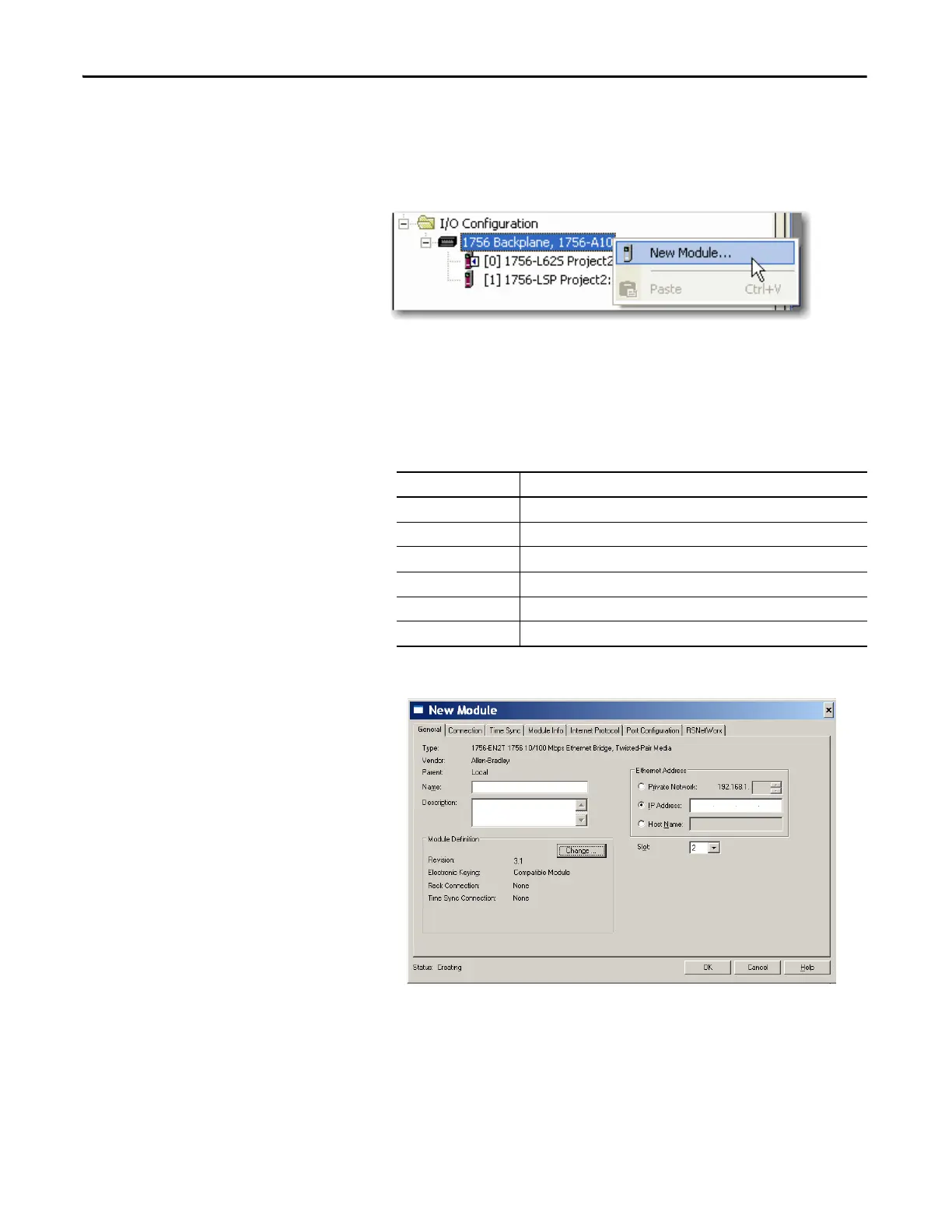
1. From the I/O Configuration tree, right-click 1756 Backplane, 1756-Axx,
and choose New Module.
2. In the Select Modules dialog box, check Communication and
Allen-Bradley®.
3. Choose an Ethernet module from the list and click Create.
In this example, we chose the 1756-EN2T bridge. These module revisions
support CIP Safety.
4. Specify the properties for the new module.
a. In the Name field of the New Module dialog box, type the name of the
Ethernet bridge.
b. In the Description field, type an optional description.
c. In the IP address field, type the IP address.
d. In the Slot field, choose the slot number.
Cat. No. Compatible Major Revision
1756-EN2F 1 or later
1756-EN2T 1 or later
1756-ENBT 3 or later
1756-EN2TR 3 or later
1756-EN3TR 3 or later
1768-ENBT 3 or later
 Loading...


