Rockwell Automation Publication 1734-UM013N-EN-P - September 2017 99
Configure the Module in a GuardLogix Controller System Chapter 5
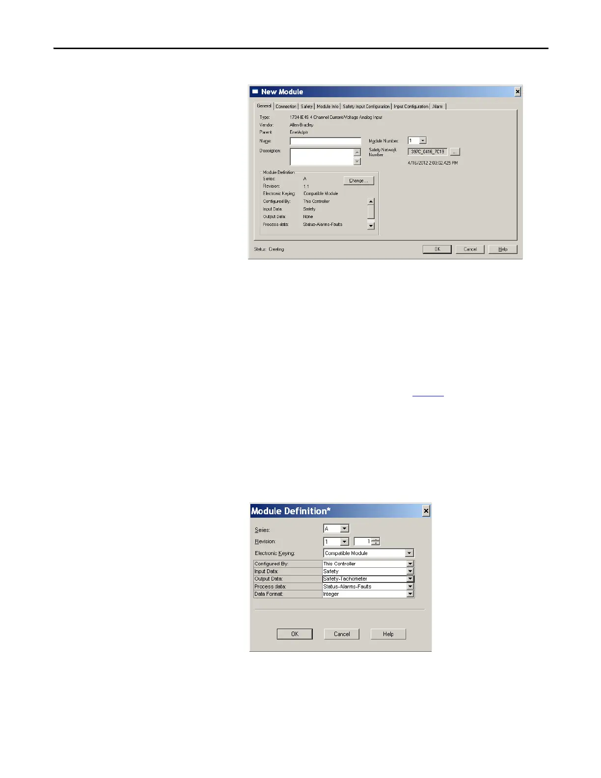
3. Specify the general properties of the module.
a. In the Name field of the New Module dialog box, type a unique name
for the analog input module.
b. From the Module Number pull-down menu, choose a unique module
number that corresponds to the position of the module in the chassis.
c. In the Description field, type a description, if desired.
d. In the Safety Network Number field, use the default setting.
For a detailed explanation of the safety network number (SNN), see the
GuardLogix Controller Systems Safety Reference Manuals that are
listed in the Additional Resources on page 14
. In most cases, you use
the default that is provided by the Logix Designer application.
The safety network number (SNN) is a unique number that identifies a
safety subnet. We suggest that all safety modules on a network have the
same SNN, to make documentation easier. During configuration, the
Logix Designer application defaults the SNN of a safety device to
match the SNN of the lowest safety node on the network.
4. To open the Module Definition dialog box, click Change.
a. In the Series field, choose the series letter of the analog input module.
b. In the Revision fields, choose the revision number of the module.
 Loading...


