172 Rockwell Automation Publication 1734-UM013N-EN-P - September 2017
Appendix B Get I/O Diagnostic Status from Modules in Logix Systems
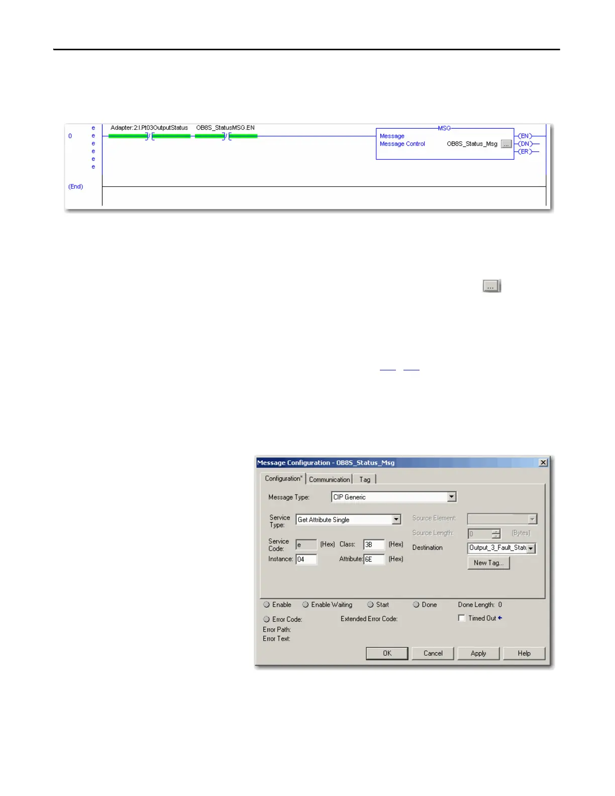
This sample ladder logic is monitoring the status of output point 3. This ladder
logic rung examines the Output Point Status and, when a fault is detected
(0 = error), the message instruction is executed.
Configure the
Message Instruction
Follow this procedure to edit the Message Configuration dialog box.
1. In the Message Instruction in the ladder logic, click the icon.
2. On the Configuration tab, enter the appropriate data for what you want to
monitor.
a. From the Service Type pull-down menu, choose Get Attribute Single.
b. Enter the Class, Instance, and Attribute data, that refers to the
appropriate tables on pages 173
…174.
3. On the Communication tab, specify the path for the message.
This example illustrates values that you enter to determine the reason for the fault
on Output 3.
Figure 52 - Message Instruction Configuration Example
When entering the Instance value, enter the input/output point plus 1
In this example, Output Point 3 is Instance 4.
 Loading...


