Rockwell Automation Publication 1734-UM013N-EN-P - September 2017 65
Install the Module Chapter 4
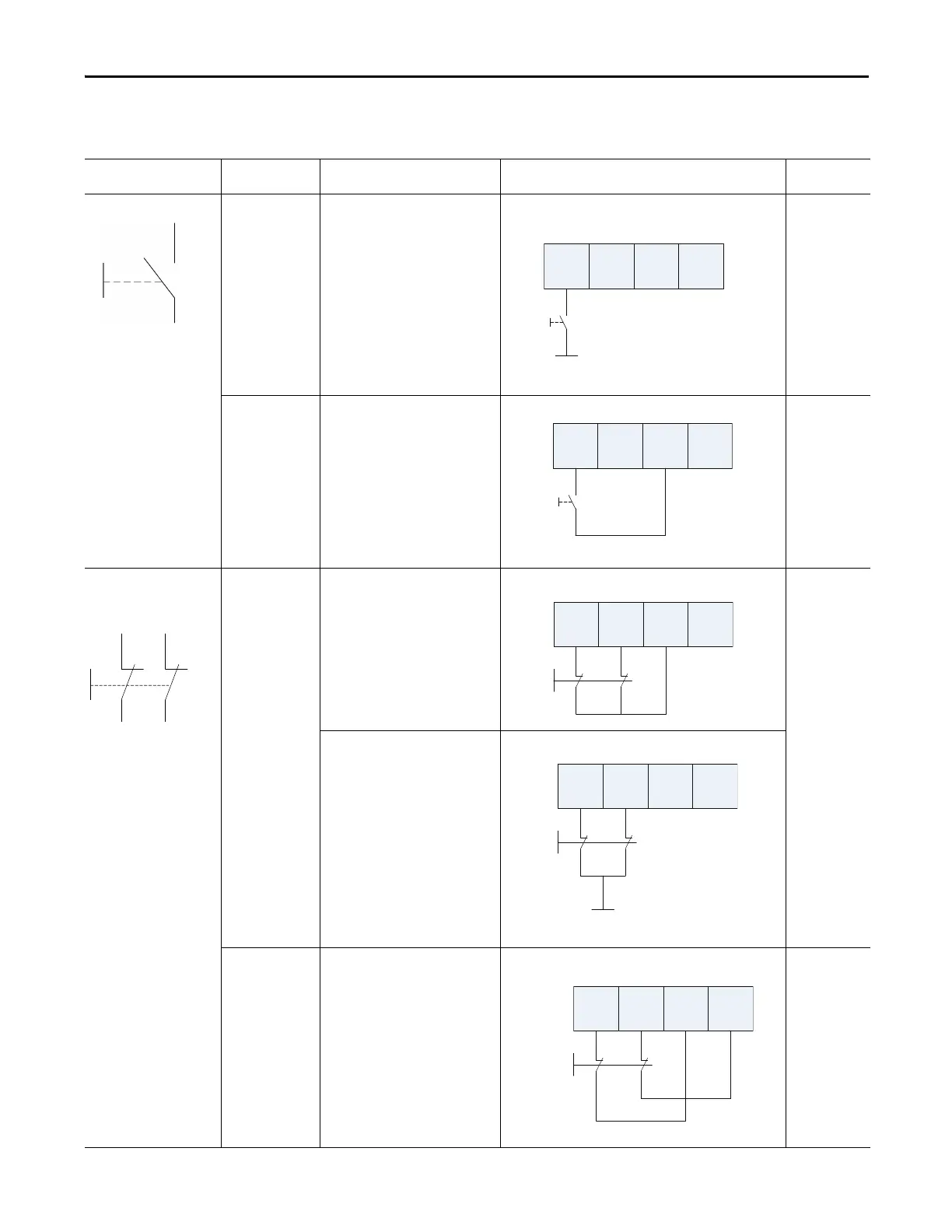
Connection Details
See the tables that show input device connection methods and their safety
categories.
Connected Device Test Pulse from
Test Output
Connection Schematic Diagram Safety
Category
Push Button No Connect the push button between 24V
DC and I0.
1
Yes Connect the push button between I0
and T0. T0 must be configured as test
pulse.
2
Emergency stop button
Door monitoring switch
No Connect the devices between T0 and I0
and I1, note that T0 is configured for 24V
power supply.
3
Connect the devices between 24V DC
and I0 and I1.
Yes Connect the device between I0 and T0,
and I1 and T1.
4
I0 I1 T0 T1
I0 I1 T0 T1
24V DC
 Loading...


