Rockwell Automation Publication 5000-UM005B-EN-P - November 2015 111
Calibrate the Module Chapter 7
Difference Between
Calibrating an Input Module
and an Output Module
The purpose of calibrating the 5069 Compact I/O analog I/O modules is the
same for input and output modules, to improve the module’s accuracy and
repeatability. The procedures involved differs by module type:
• When you calibrate input modules, you use current, voltage, or ohms
reference signals to send a signal to the module to calibrate it.
• When you calibrate output modules, you use a digital multimeter (DMM)
to measure the current or voltage signal the module is sending out.
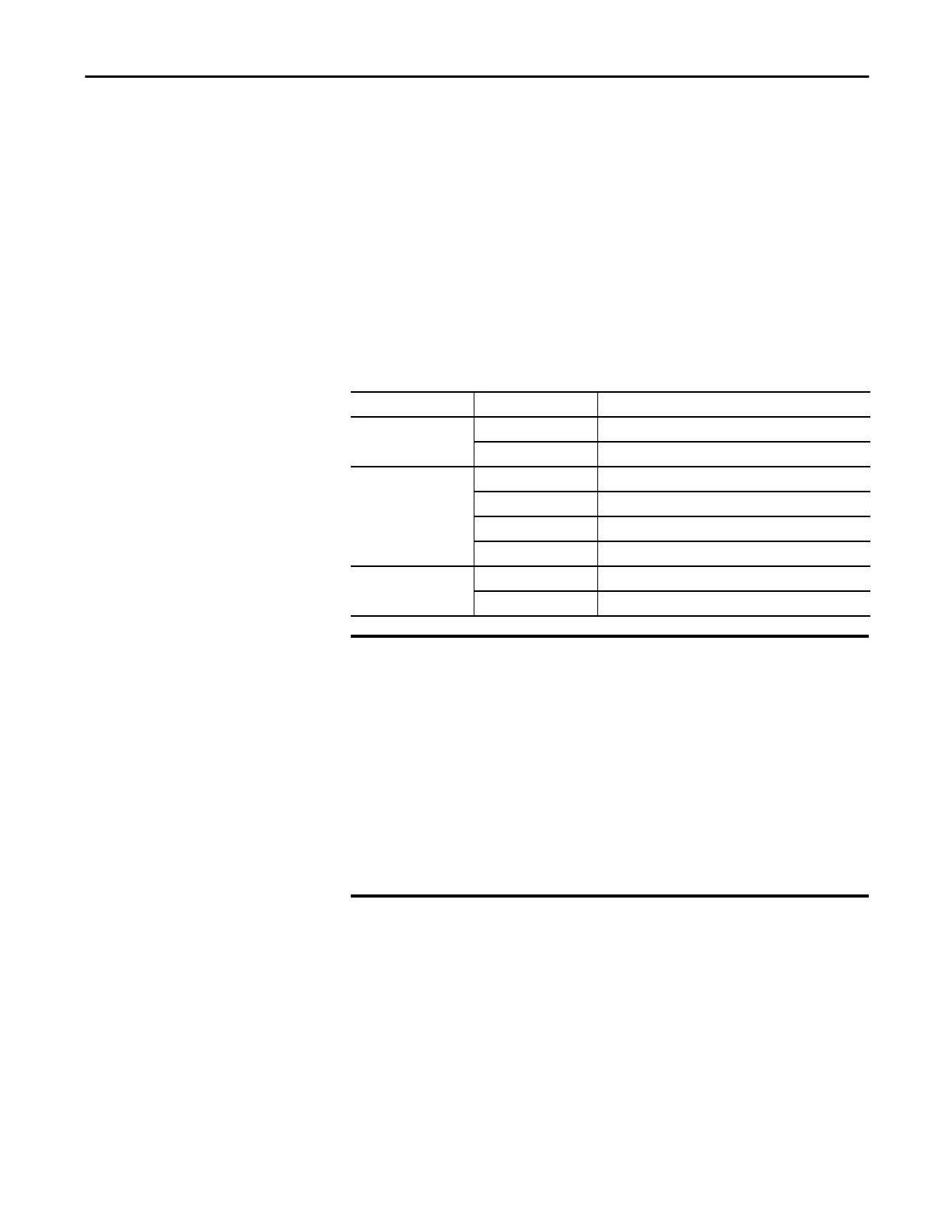
To maintain your module's factory calibration accuracy, we recommend
instrumentation with the specifications listed below. A high resolution DMM
can also be used to adjust a voltage/current calibrating source to its value.
Cat. No. Channel Input Type Recommended Instrument Specifications
5069-IF8
Current (mA) 1.00…20.00 mA source ±100 nA current
Voltage (V) 0…10V source ±2 μV voltage
5069-IY4
Current (mA) 1.00…20.00 mA source ±100 nA current
Voltage (V) 0…10V source ±2 μV voltage
RTD 1.0…487.0 resistors ±0.01%
Thermocouple (mV) 0…100 mV source ±0.5 μV
5069-OF4, 5069-OF8
Current (mA) DMM with resolution better than 0.15 μA
Voltage (V) DMM with resolution better than 1.0 μV
IMPORTANT
Do not calibrate your module with an instrument that is less accurate than
those recommended. The following events can result:
• Calibration appears to occur normally but the module gives inaccurate
data during operation.
• A calibration fault occurs, forcing you to abort calibration.
• The I.Chxx.CalFault tag is set for the channel you attempted to calibrate.
You can clear the tag by completing a valid calibration or cycling power
to the module. In this case, you must recalibrate the module with an
instrument as accurate as recommended.

 Loading...

