Rockwell Automation Publication 5000-UM005B-EN-P - November 2015 49
Current/Voltage Analog Input Module Features (5069-IF8) Chapter 3
Fault and Status Reporting
The 5069-IF8 module sends fault and status data with channel data to the owner-
controller and listening controllers. The data is returned via module tags that you
can monitor in your Logix Designer application.
With some exceptions, the 5069-IF8 module provides the fault and data status in
a channel-centric format. The tag names in the following table that include Chxx
represent channel-centric data. The xx represents channel number.
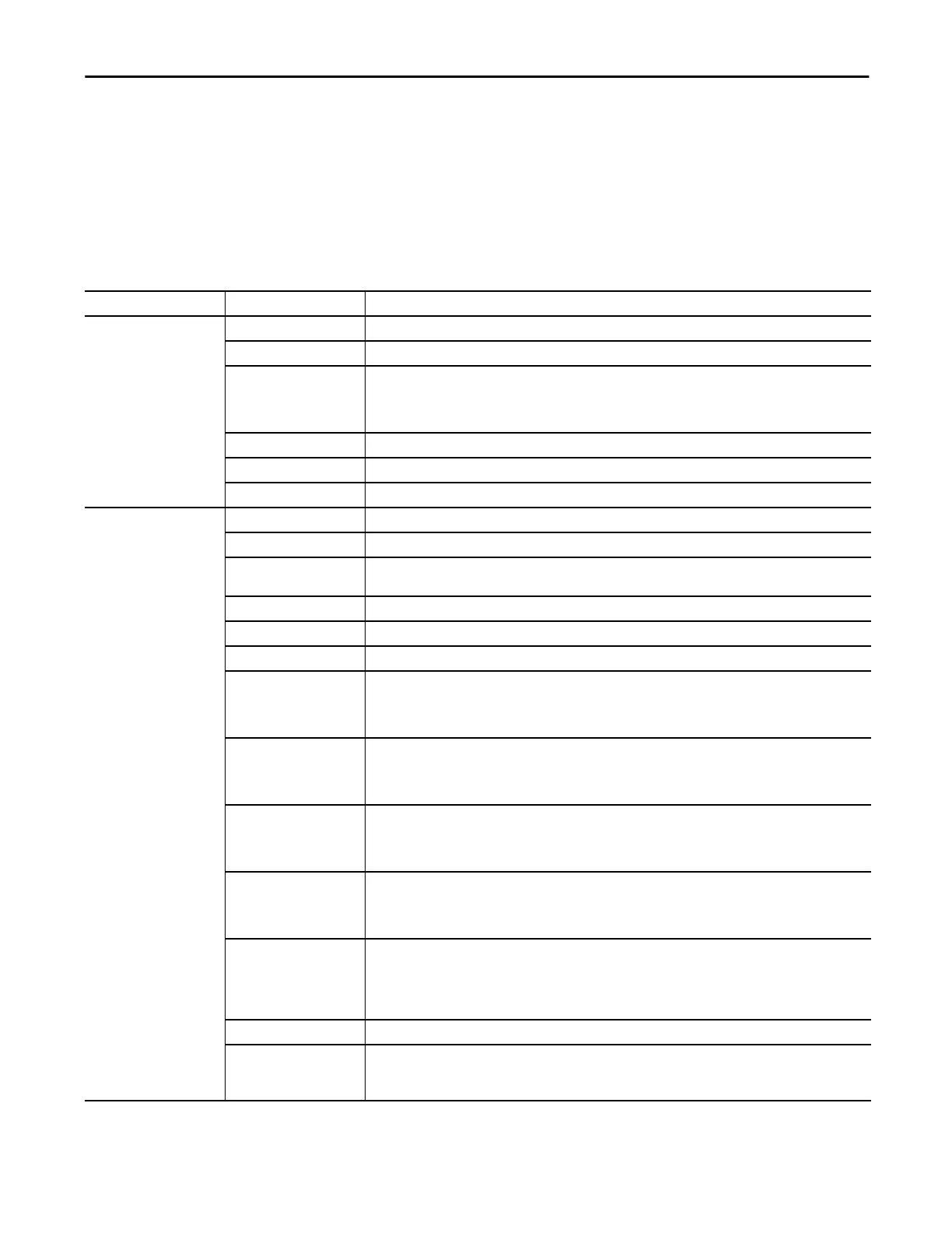
Table 11 - 5069-IF8 Module - Fault and Status Data Tags
Data Type Tag Name Triggering Event That Sets Tag
Fault
ConnectionFaulted
(1)
The owner-controller loses its connection to the module.
Chxx.Fault The channel data quality is bad.
Chxx.OpenWire The following conditions:
• The channel uses a Voltage input type in any input range and the input signal value reaches full scale.
• The channel uses a Current input type in only the 4…20 mA input range and the input signal goes below 100
μA. The input signal at the channel is below 100 μA.
Chxx.Underrange The channel data is beneath the absolute minimum for this channel.
Chxx.Overrange The channel data is above the absolute maximum for this channel.
Chxx.OverTemperature The module is at a higher temperature than its rated operating limits.
Status
RunMode
(1)
The module is in Run Mode.
DiagnosticActive Indicates if any diagnostics are active or if the prognostics threshold is reached.
DiagnosticSequenceCount A counter that increments when a diagnostic condition occurs or goes away. The counter is a rolling counter that
skips 0 on rollovers.
Chxx.Uncertain The channel data can be imperfect but it is not known to what degree of inaccuracy.
Chxx.FieldPowerOff Field power is not present on the channel.
Chxx.NotANumber The most recently received data value was not a number.
Chxx.LLAlarm The following conditions exist:
• The I.Chxx.Data tag value is less than the C.Chxx.LLAlarmLimit tag value or the alarm is latched.
• The O.Chxx.LLAlarmEn tag is set.
• Alarms are enabled for the channel.
Chxx.LAlarm The following conditions exist:
• The I.Chxx.Data tag value is less than the C.Chxx.LAlarmLimit tag value or the alarm is latched.
• The O.Chxx.LAlarmEn tag is set.
• Alarms are enabled for the channel.
Chxx.HAlarm The following conditions exist:
• The I.Chxx.Data tag value is greater than the C.Chxx.HAlarmLimit tag value or the alarm is latched.
• The O.Chxx.HAlarmEn tag is set.
• Alarms are enabled for the channel.
Chxx.HHAlarm The following conditions exist:
• The I.Chxx.Data tag value is greater than the C.Chxx.HHAlarmLimit tag value or the alarm is latched.
• The O.Chxx.HHAlarmEn tag is set.
• Alarms are enabled for the channel.
Chxx.RateAlarm The following conditions exist:
• The absolute change between consecutive channel samples exceeds the C.Chxx.RateAlarmLimit tag value or the
alarm is latched.
• The O.Chxx.RateAlarmEn tag is set.
• Alarms are enabled for the channel.
Chxx.Data The channel data in scaled Engineering Units.
RollingTimestamp
(1)
A continuously running, 15-bit timer that counts in milliseconds and is not related to the CST.
Whenever a module scans its channels, it records the value of RollingTimestamp then. The controller program uses
the last two rolling timestamp values to calculate the amount of time between the samples.
(1) This tag provides module-wide data and affects all channels simultaneously.

 Loading...

