118 Rockwell Automation Publication 5000-UM005B-EN-P - November 2015
Chapter 7 Calibrate the Module
Calibrate the
Output Modules
When calibrating a 5069 Compact I/O analog output channel, the Logix
Designer application commands the module to output specific signal levels. The
signal type is determined by the output type being used by the channel.
Table 25 lists the output ranges and corresponding references used to calibrate
the module.
You must measure the actual level and record the results to account for any
module inaccuracies.
Calibrate a 5069-OF8 Module
This example describes how to calibrate a channel on the 5069-OF8 module for
use with a Voltage (V) output type. Complete the following steps:
1. Connect the DMM to the channel being calibrated.
2. Go online with the project and make sure the controller is in
Program mode.
3. Confirm that the channel to be calibrated is configured for the correct
Output Range.
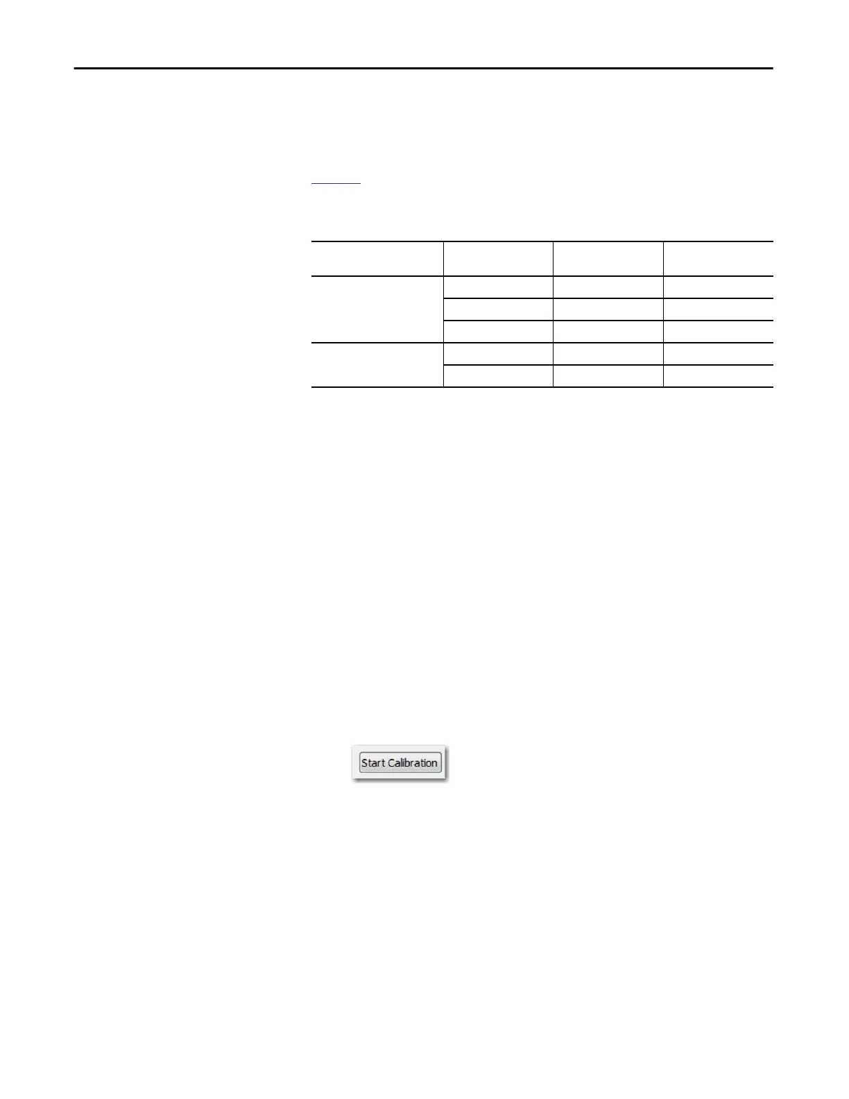
4. On the Calibration category in the Module Properties dialog box, click
Start Calibration.
Table 26 - 5069 Compact I/O Analog Output Module Calibration References
Output Type Output Range Low Calibration
Reference Level
High Calibration
Reference Level
Voltage (V) -10…10V -10.0V 10.0V
0…10V 1.0V 10.0V
0…5V 1.0V 5.0V
Current (mA) 0…20 mA 1.0 mA 20.0 mA
4…20 mA 5.0 mA 20.0 mA

 Loading...

