42 Rockwell Automation Publication 5000-UM005B-EN-P - November 2015
Chapter 3 Current/Voltage Analog Input Module Features (5069-IF8)
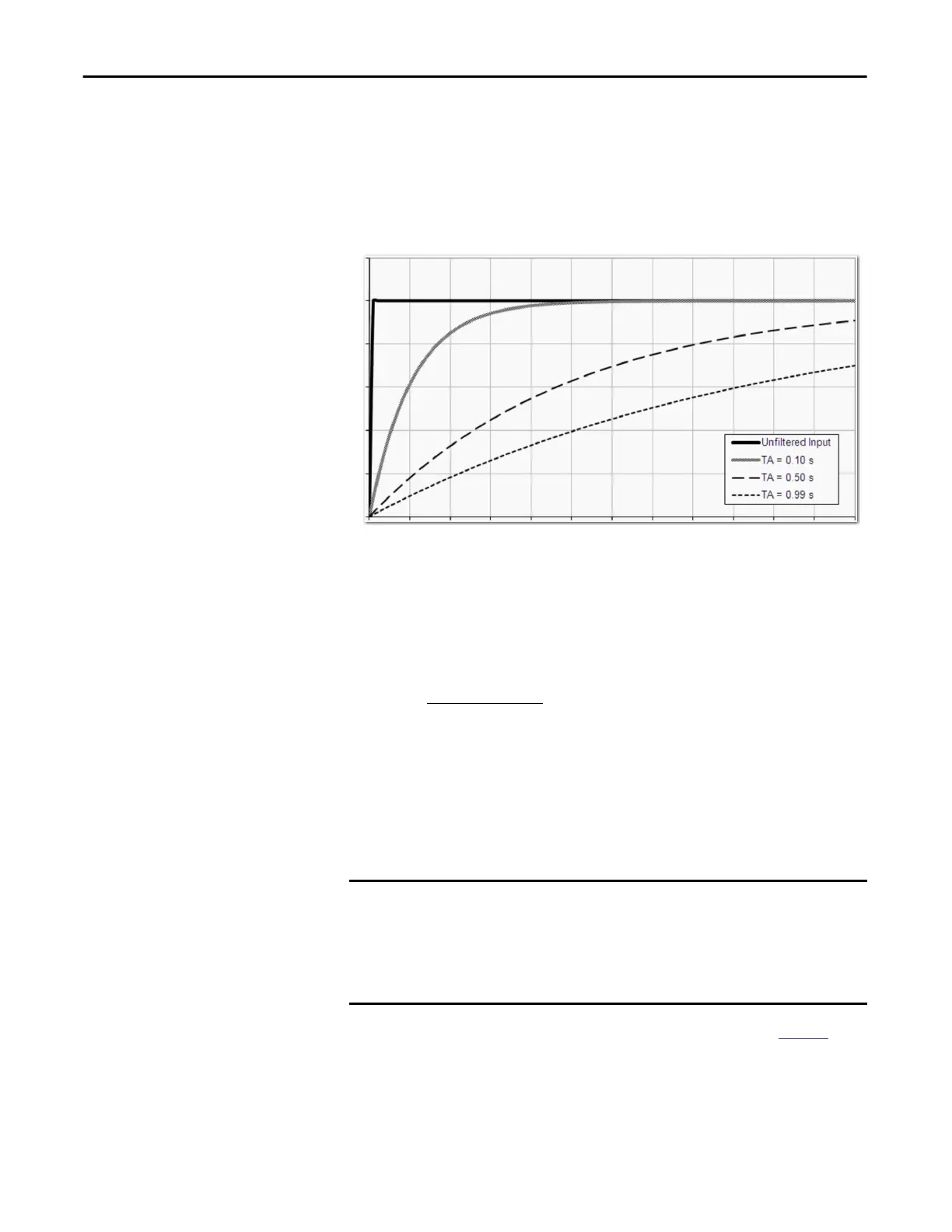
Digital Filter
The Digital Filter is a first-order lag filter. It smooths input data noise transients
on each input channel. This value specifies the time constant for a digital, first-
order lag filter on the input. The input is 63% of the step change after the first
time constant elapses.
The filter value is specified in units of milliseconds. A value of 0 (zero) disables
the filter. The digital filter equation is as shown.
To see where to choose a digital filter for the 5069-IF8 module, see
page 93.
0.1
Time in Seconds
20
0
Amplitude %
0.2 0.3 0.4 0.5 0.6 0.7 0.8 0.9 1.0 1.1 1.2
40
60
80
100
120
Y
n
= Y
n
-1
+
(X
n
- Y
n
-1)
t
t + TA
Y
n
= Present Output, Filtered Peak Voltage (PV)‘
Y
n
-1
= Previous Output, Filtered PV
t = Module Channel Update Time (seconds)
TA = Digital Filter time Constant (seconds)
X
n
= Present Input, Unfiltered PV
*
IMPORTANT
Remember the following:
• Digital Filter input data changes only when new input data is collected.
• If an Overrange or Underrange condition is detected before the Digital
Filter input data is collected, the condition is indicated immediately. An
immediate indication also applies to the Fault data for the input.

 Loading...

