142 Rockwell Automation Publication 5000-UM005B-EN-P - November 2015
Appendix B Module Tag Definitions
5069-IY4 Module Tags
This section describes the tags associated with the 5069-IY4 module.
Configuration Tags
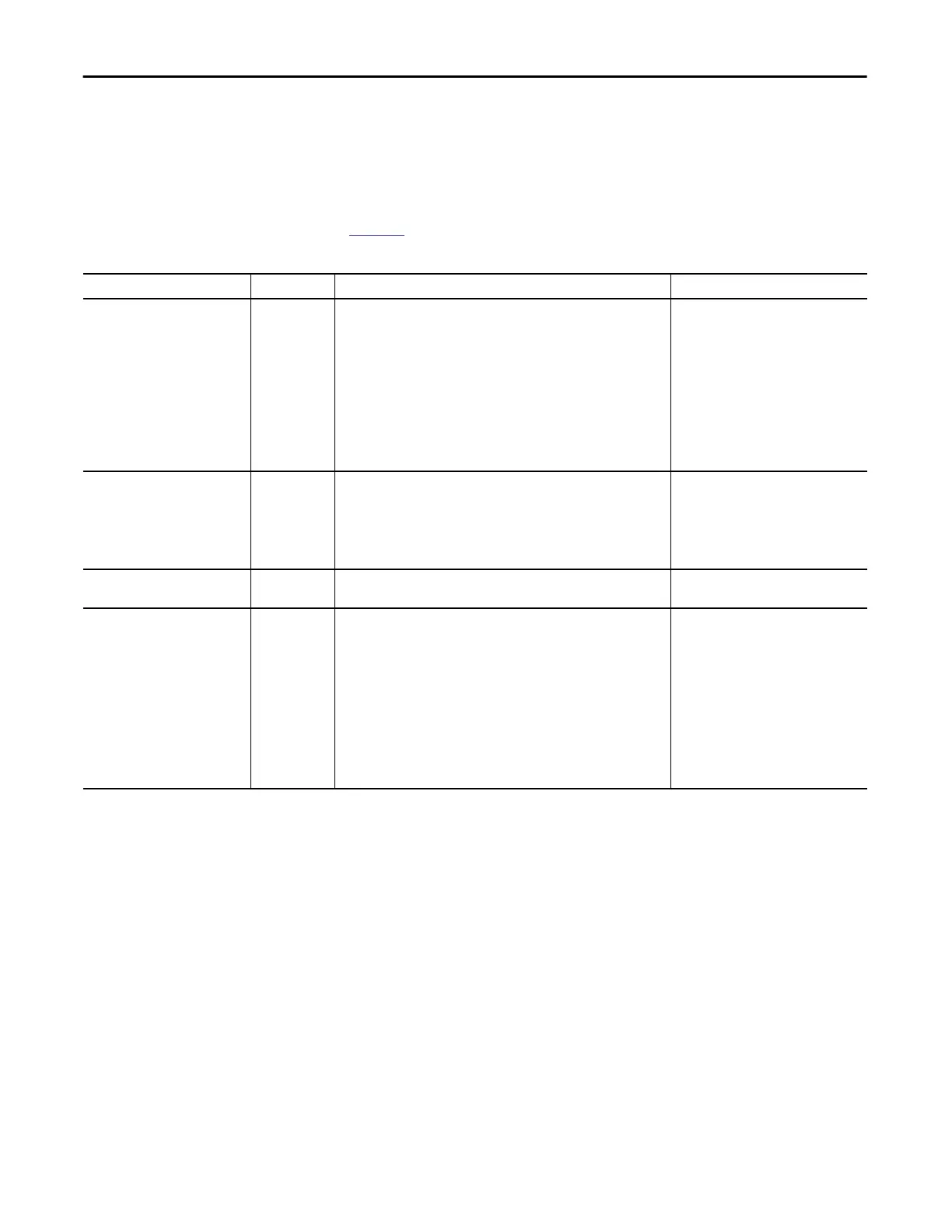
Table 33 describes the 5069-IY4 module configuration tags.
Table 33 - 5069-IY4 Module - Configuration Tags
Name Size Definition Valid Values
CJChxx.Disable BOOL The CJ measurement is not used when the module calculates the CJ
compensation.
There are two CJ measurements that can be taken on the module. The
combination of configuration values determines how CJ compensation is
affected. Consider the following:
• If you enable CJCh00 and CJCh01 measurements, both measurements
are used to calculate CJ compensation.
• If you enable only one CJChxx measurement, only that measurement is
used to calculate CJ compensation.
• If you disable both CJChxx measurements, it is assumed that the cold
junction temperature is 0 in the CJ compensation.
• 0 = Cold junction measurement is used
to calculate CJ compensation
• 1 = Cold junction measurement is not
used to calculate CJ compensation
CJChxx.Remote BOOL Indicates if the cold junction sensor is mounted on a remote termination
block when set, rather than on the local terminal block. Needed for proper
cold junction compensation when linearizing thermocouples.
If the cold junction sensor is mounted on a remote termination block,
CJCh00 is used with channels 00 and 01 and CJCh01 is used with channels 02
and 03.
• 0 = Cold junction sensor is not
mounted on a remote termination
block
• 1 = Cold junction sensor is mounted on
a remote termination block
CJChxx.SensorOffset REAL Offset added directly to the measured CJ temperature. Used to compensate
for cold junction temperature sensor error.
Any
Chxx.Range SINT Channel’s operating range • 0 = -10…10V
• 1 = 0…5V
• 2 = 0…10V
• 4 = 0…20 mA
• 5 = 4…20 mA
• 6 = -100...100 mV
• 7 = unused
• 8 = 1…500 Ω
• 9 = 2…1,000 Ω
• 10 = 4…2,000 Ω
• 11 = 8…4,000 Ω

 Loading...

