Rockwell Automation Publication 1756-RM100F-EN-P - October 2018 55
Replacement Considerations with CompactLogix and Compact GuardLogix Systems Chapter 3
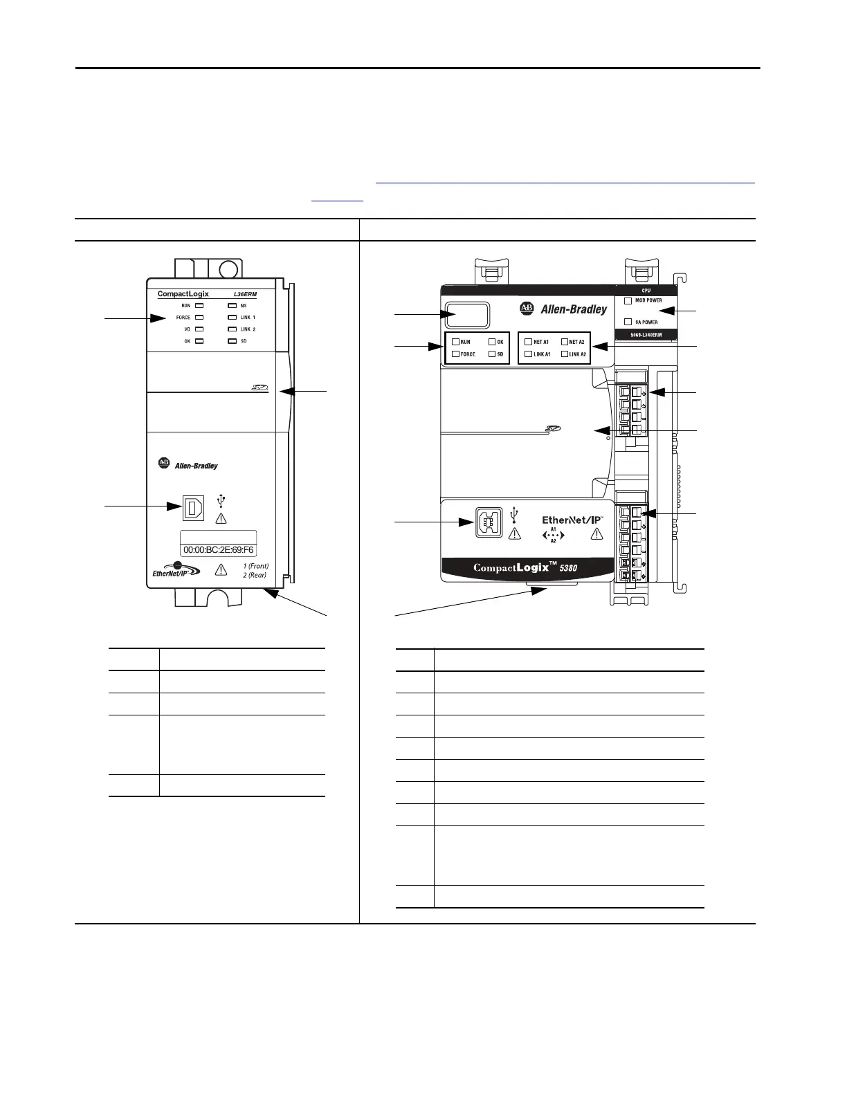
Connectors and
Status Indicators
The following tables shows the differences between the connectors and status
indicators.
For more information on the controller status indicators and reset button, see
Chapter 8, Diagnostics and Status Indicators with CompactLogix Systems on
page 149.
CompactLogix 5370 L3 CompactLogix 5380
Item Description
1 Status Indicators
2USB port
3 Behind the door:
• RUN REM PROG mode switch
• Reset button
•SD card slot
4 Ethernet ports 1 and 2
1
2
3
4
1
9
4
3
5
7
2
Item Description
14-character display
2 Controller Status Indicators
3USB port
4 Ethernet ports 1 and 2
5 Power Status Indicators
6 EtherNet/IP Status Indicators
7 MOD power connection
8 Behind the door:
• RUN REM PROG mode switch
• Reset button
•SD card slot
9 SA power connection
6
8

 Loading...


