Publication 1763-RM001C-EN-P - October 2009
ASCII Instructions 313
Addressing String Files
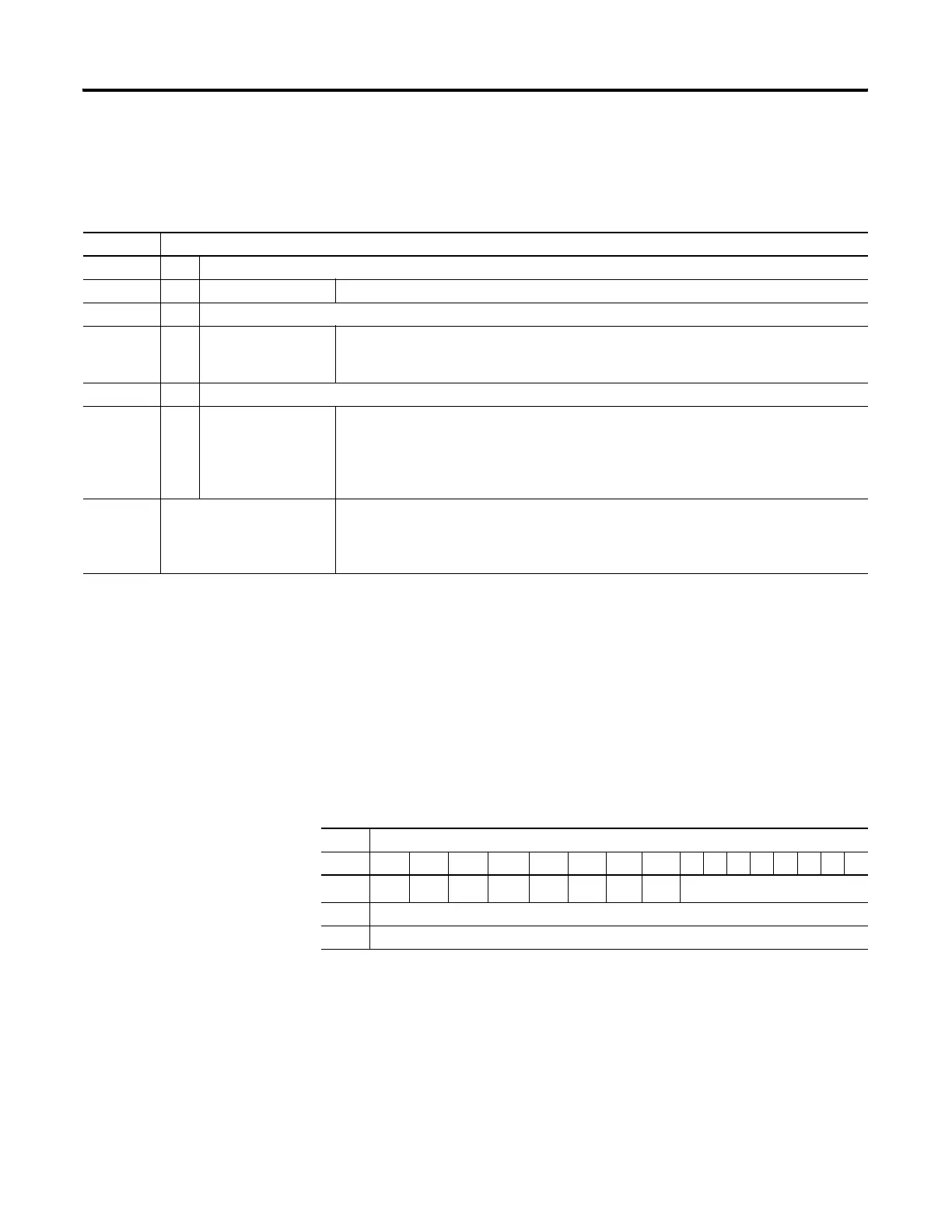
The addressing scheme for the string data file is shown below.
Control Data File
File Description
The control data element is used by ASCII instructions to store control
information required to operate the instruction. The control data element
for ASCII instructions includes status and control bits, an error code byte,
and two character words as shown below:
Format Explanation
ST String file
STf:e.s f File number The valid file number range is from 3 to 255.
: Element delimiter
e Element number The valid element number range is from 0 to 255.
Each element is 42 words in length as shown in .
. Subelement delimiter
s Subelement number The valid subelement number range is from 0 to 41.
You can also specify .LEN for word 0 and .DATA[0] through .DATA[40] for words 1 to 41.
The subelement represents a word address.
Examples: ST9:2
ST17:1.LEN
ST13:7.DATA[1]
String File 9, Element 2
String File 17, Element 1, LEN Variable
String File 13, Element 7, word 2 (characters 2 and 3)
ASCII Instructions Control Data File Elements
Control Element
Word 15 14 13 12 11 10 09 08 07 06 05 04 03 02 01 00
0
EN
(1)
(1) EN = Enable Bit - indicates that an instruction is enabled due to a false-to-true transition. This bit remains set until the
instruction completes execution or generates an error.
EU
(2)
(2) EU = Queue Bit - when set, indicates that an ASCII instruction was placed in the ASCII queue. This action is delayed if
the queue is already filled.
DN
(3)
(3) DN = Asynchronous Done Bit - is set when an instruction successfully completes its operation.
EM
(4)
(4) EM = Synchronous Done Bit - not used
ER
(5)
(5) ER = Error Bit - when set, indicates that an error occurred while executing the instruction.
UL
(6)
RN
(7)
FD
(8)
Error Code Byte
1 Number of characters specified to be sent or received (LEN)
2 Number of characters actually sent or received (POS)
efesotomasyon.com - Allen Bradley,Rockwell,plc,servo,drive
 Loading...


