Publication 1763-RM001C-EN-P - October 2009
134 Using High-Speed Outputs
Pulse Train Output
Function File
Sub-Elements Summary
The variables within each PTO sub-element, along with what type of
behavior and access the control program has to those variables, are listed
individually below. All examples illustrate PTO 0. Terms and behavior for
PTO 1 are identical.
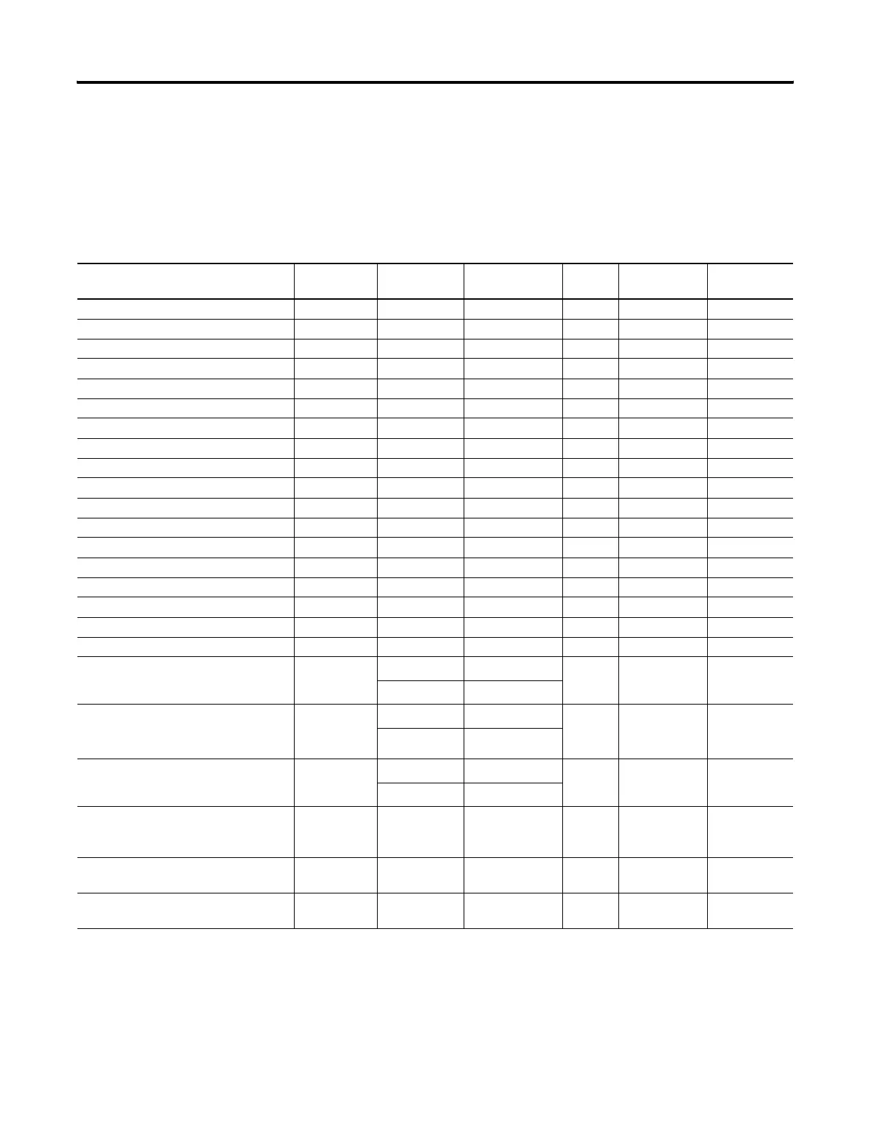
Pulse Train Output Function File (PTO:0)
Sub-Element Description Address Data Format Range Type User Program
Access
For More
Information
OUT - Output PTO:0.OUT word (INT) 2 or 3 control read only 135
DN - Done PTO:0/DN bit 0 or 1 status read only 135
DS - Decelerating Status PTO:0/DS bit 0 or 1 status read only 136
RS - Run Status PTO:0/RS bit 0 or 1 status read only 136
AS - Accelerating Status PTO:0/AS bit 0 or 1 status read only 136
RP - Ramp Profile PTO:0/RP bit 0 or 1 control read/write 137
CS - Controlled Stop PTO:0/CS bit 0 or 1 control read/write 144
IS - Idle Status PTO:0/IS bit 0 or 1 status read only 137
ED - Error Detected Status PTO:0/ED bit 0 or 1 status read only 138
NS - Normal Operation Status PTO:0/NS bit 0 or 1 status read only 138
JPS - Jog Pulse Status PTO:0/JPS bit 0 or 1 status read only 146
JCS - Jog Continuous Status PTO:0/JCS bit 0 or 1 status read only 147
ADI - Accel/Decel Pulses Independent PTO:0/ADI bit 0 or 1 control read/write 141
JP - Jog Pulse PTO:0/JP bit 0 or 1 control read/write 146
JC - Jog Continuous PTO:0/JC bit 0 or 1 control read/write 147
EH - Enable Hard Stop PTO:0/EH bit 0 or 1 control read/write 138
EN - Enable Status (follows rung state) PTO:0/EN bit 0 or 1 status read only 139
ER - Error Code PTO:0.ER word (INT) -2 to 7 status read only 148
OF
(1)
(2)
- Output Frequency (Hz)
PTO:0.OF
word (INT)
(3)
0 to 20,000
(3)
control read/write 139
word (UINT)
(4)
0 to 40,000
(4)
OFS
(1)
- Operating Frequency
Status (Hz)
PTO:0.OFS
word (INT)
(3)
0 to 20,000
(3)
status read only 140
word (UINT)
(4)
0 to 40,000
(4)
JF
(1)
(2)
- Jog Frequency (Hz)
PTO:0.JF
word (INT)
(3)
0 to 20,000
(3)
control read/write 145
word (UINT)
(4)
0 to 40,000
(4)
TOP - Total Output Pulses
To Be Generated
PTO:0.TOP long word
(32-bit INT)
0 to
2,147,483,647
control read/write 140
OPP - Output Pulses Produced PTO:0.OPP long word
(32-bit INT)
0 to
2,147,483,647
status read only 141
ADP - Accel/Decel Pulses PTO:0.ADP long word
(32-bit INT)
see p. 142 control read/write 142
(1) OF, OFS, and JF are signed 16-bit (-32768~32768) variables in MicroLogix 1100 Series A controller, but they are unsigned 16-bit (0~65535) variables in MicroLogix 1100
Series B controller.
(2) The variable range of OF, OFS, and JF is 0~20000 in MicroLogix 1100 Series A controller and it is 0~40000 in MicroLogix 1100 Series B controller.
(3) Applies only to MicroLogix 1100 Series A Controller
(4) Applies only to MicroLogix 1100 Series B Controller
efesotomasyon.com - Allen Bradley,Rockwell,plc,servo,drive

 Loading...


